The value for one of these conditions is shown for
two seconds. Then, the display scrolls to the value for
the next condition. A small pointer identifies the
engine condition that corresponds to the value which
is showing. When the engine meter key (30) is
pressed, the lower display (27) stops scrolling. The
lower display (27) continuously shows one particular
value. The pointer flashes when the indicated value
is above a predetermined value. When engine meter
key (30) is pressed for a second time, the display
(27) will return to scrolling.
The relay status indicators are on the bottom of the
lower display (27). When a GSC relay is activated,
the corresponding indicator (K1, K2, etc) is shown on
lower display (27). When a relay is not activated, the
corresponding indicator (K1, K2, etc) is not shown.
For a description of the relay functions, see the
Systems Operation, Testing and Adjusting,
SENR5809, “Electronic Modular Control Panel II
(EMCP II) for MUI Engines” or the Systems
Operation, Testing and Adjusting, SENR5398,
“Electronic Modular Control Panel II (EMCP II) for
EUI Engines”.
Keypad
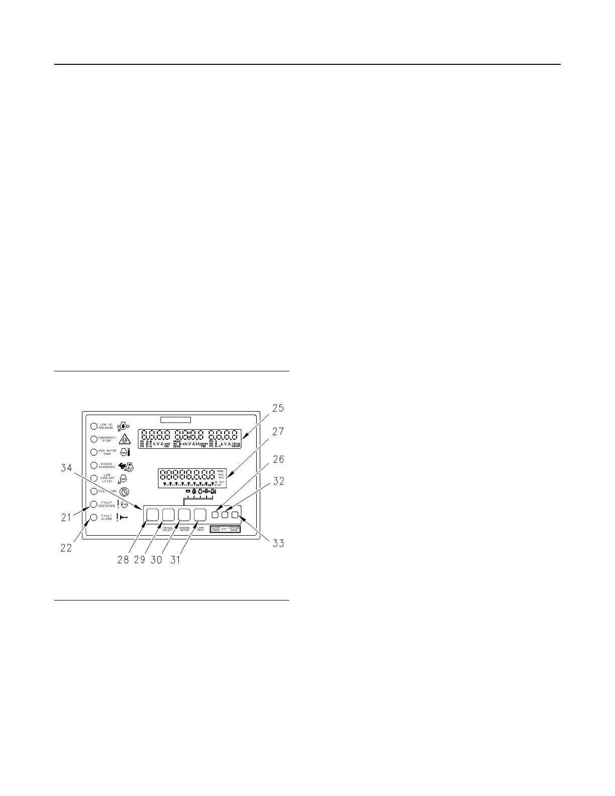
Illustration 52 g00636347
Keypad Area of the GSC
(21) Fault shutdown indicator
(22) Fault alarm indicator
(25) Upper display
(26) The alarm codes key
(27) Lower display
(28) Leftmost key
(29) Phase select key
(30) Engine meter key
(31) Lamp test key
(32) Exit key
(33) Service mode key
(34) Keypad
Keypad (34) is used to control the information that is
shown on upper display (25) and lower display (27).
The seven keys have two sets of functions: normal
functions and service functions. For a description of
the service functions of the keys, see the Systems
Operation, Testing and Adjusting, SENR5809,
“Electronic Modular Control Panel II (EMCP II) for
MUI Engines” or see the Systems Operation, Testing
and Adjusting, SENR5398, “Electronic Modular
Control Panel II (EMCP II) for EUI Engines”. The
normal functions of the keys are described in the
following paragraphs.
Leftmost Key (28) – This key only functions when
the GSC is in service mode. This key is used to scroll
right.
Phase Select Key (29) – This key selects the phase
of the generator output that is displayed on the GSC.
When you press this key, the display shows the
voltage, current, and frequency of each phase one at
a time.
Engine Meter Key (30) – This key controls the
viewing of engine parameters on the lower display.
Pressing the key stops the scrolling of engine
conditions. The value for one particular engine
condition will show continuously. The pointer flashes
indicating that the scrolling is stopped. The scrolling
of the engine conditions will resume when the engine
meter key is pressed again.
Lamp Test Key (31) – Pressing this key performs a
lamp test on the GSC and the optional alarm module.
On the GSC, the eight fault indicators are ON
CONTINUOUSLY. Every segment of upper display
(5) and lower display (6) is ON. On the optional alarm
module, all of the indicators are ON and the horn
sounds. The lamp test function automatically turns off
when an operator presses the key and the operator
holds the key for more than ten seconds.
The Alarm Codes Key (26) – If fault alarm indicator
(22) is FLASHING, pressing this key causes upper
display (25) to show the corresponding alarm fault
code. If this key is pressed again, the generator AC
output information will be shown on the upper display
(25). If fault alarm indicator (22) is OFF, this key has
no function.
Exit Key (32) – This key only functions when the
GSC is in Service Mode. For more information, see
the Systems Operation, Testing and Adjusting,
SENR5809, “Electronic Modular Control Panel II
(EMCP II) for MUI Engines” or see the Systems
Operation, Testing and Adjusting, SENR5398,
“Electronic Modular Control Panel II (EMCP II) for
EUI Engines”.
Service Mode Key (33) – Pressing this key causes
the GSC to enter service mode. For more
information, see the Systems Operation, Testing and
Adjusting, SENR5809, “Electronic Modular Control
Panel II (EMCP II) for MUI Engines” or see the
Systems Operation, Testing and Adjusting,
SENR5398, “Electronic Modular Control Panel II
(EMCP II) for EUI Engines”.
SEBU7125-13
41
Operation Section
If Equipped
 Loading...