Fault indicators
Illustration 57 g00643441
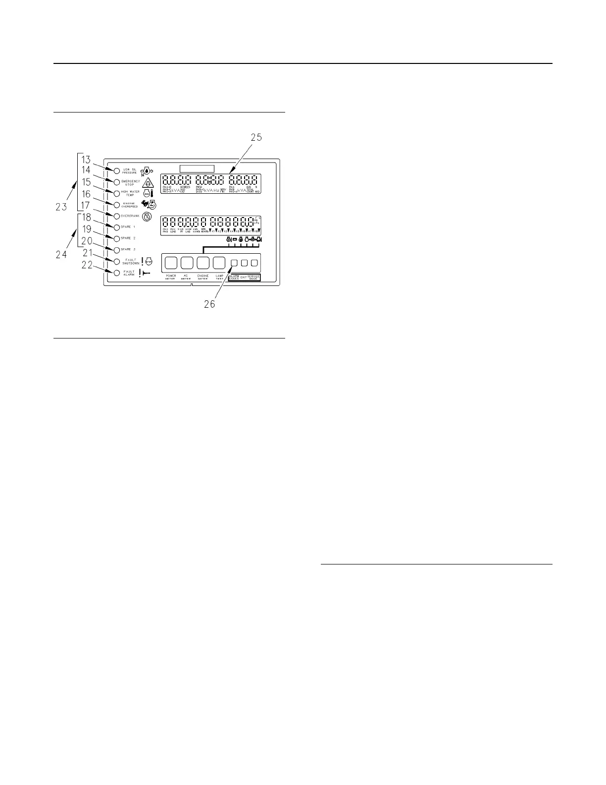
Display Area of the GSC+
(13) Low oil pressure indicator
(14) Emergency stop indicator
(15) High water temperature indicator
(16) Engine overspeed indicator
(17) Overcrank indicator
(18) Spare 1 indicator
(19) Spare 2 indicator
(20) Spare 3 indicator
(21) Fault shutdown indicator
(22) Fault alarm indicator
(23) Dedicated shutdown indicators
(24) Spare fault indicators
(25) Upper display
(26) The alarm codes key
The ten fault indicators are used in order to show and
describe a fault that is present. The fault indicators
are divided into four groups. The four groups are:
• fault alarm indicator (22)
• fault shutdown indicator (21)
• spare fault indicators (24)
• dedicated shutdown indicators (23)
The yellow fault alarm indicator (22) FLASHES when
the GSC+ detects an alarm fault. The alarm fault
does not cause the engine status to change. The
engine can be started. The engine will continue
operating only if the engine is running at the time of
the alarm fault. Fault alarm indicator (22) is
accompanied by an alarm fault code that is shown on
the upper display (25) when the alarm codes key (26)
is pressed. For the descriptions of the fault codes,
refer to the Systems Operation, Testing and
Adjusting, RENR2484, “Electronic Modular Control
Panel II + (EMCP II+)”.
The red fault shutdown indicator (21) FLASHES
when the GSC+ detects a shutdown fault. The engine
will be shut down if the engine is running. The engine
will not be allowed to start. Fault shutdown indicator
(21) is accompanied by a fault code that is
immediately shown on the upper display (25). For the
descriptions of the fault codes, refer to the Systems
Operation, Testing and Adjusting, RENR2484,
“Electronic Modular Control Panel II + (EMCP II+)”.
The yellow spare fault indicators (24) FLASH when
the conditions that are associated with that spare
fault are active. The three spare faults can be
programmed to show coolant loss, oil temperature,
spare fault condition or no assignment. The spare
fault condition may be a customer generated switch
input. The yellow fault alarm indicator (22) or the red
fault shutdown indicator (21) will accompany the
spare fault indicators (24). The spare fault indicators
will tell whether the spare fault input is programmed
to be an alarm condition or a shutdown condition. For
the descriptions of the fault codes, refer to the
Systems Operation, Testing and Adjusting,
RENR2484, “Electronic Modular Control Panel II +
(EMCP II+)”.
The red dedicated shutdown indicators (23)
represent the following shutdown faults: low oil
pressure, emergency stop, high water temperature,
engine overspeed and engine overcrank. When the
GSC+ detects a fault in one of these areas, the
dedicated shutdown indicator (that corresponds to
the fault) FLASHES. The engine is shutdown if the
engine is running, and the engine is not allowed to
start. No fault codes are associated with the
dedicated shutdown indicators because each
indicator has a descriptive label.
Many of the dedicated shutdown faults depend on
certain setpoints in the GSC+. For the descriptions of
the fault codes, refer to the Systems Operation,
Testing and Adjusting, RENR2484, “Electronic
Modular Control Panel II + (EMCP II+)”.
The conditions that are required to activate the
dedicated fault shutdowns and the results of each
dedicated fault are in the following list.
Low Oil Pressure – The engine oil pressure drops
below the setpoints for low oil pressure shutdown
that are programmed into the GSC+. There are two
low oil pressure setpoints. One setpoint is used when
the engine is at idle speed. The other setpoint is used
when the engine is at rated speed. When a low oil
pressure fault occurs, the low oil pressure indicator
FLASHES, and the engine is shut down. The engine
is not allowed to start until the fault is corrected.
Emergency Stop – The operator presses the
emergency stop push button (ESPB) on the front
panel. When an emergency stop condition occurs,
the emergency stop indicator FLASHES and the
engine is shut down. The engine is not allowed to
start until the condition is corrected.
46
SEBU7125-13
Operation Section
If Equipped
 Loading...