High Water Temperature – The engine coolant
temperature rises above the setpoint for high water
temperature shutdown that is programmed into the
GSC+. When the high water temperature fault
occurs, the high water temperature indicator
FLASHES. The engine is shutdown and the engine is
not allowed to start until the fault is corrected.
Engine Overspeed – The engine speed exceeds the
setpoint for engine overspeed that is programmed
into the GSC+. When the engine overspeed fault
occurs, the engine overspeed indicator FLASHES.
The engine is shutdown and the engine is not
allowed to start until the fault is corrected.
Overcrank – The engine does not start within the
setpoint for total cycle crank time that is programmed
into the GSC+. When the overcrank fault occurs, the
overcrank indicator FLASHES. The engine is not
allowed to start until the fault is corrected.
Note: The GSC+ can be programmed to override the
shutdown for low oil pressure and high water
temperature faults. When the operator overrides the
shutdown faults, the GSC+ responds to the faults as
though the faults are alarm faults. The corresponding
dedicated shutdown indicator is ON
CONTINUOUSLY and will not be flashing. The
engine continues to run and can be restarted when
necessary. When the dedicated shutdown indicator is
ON CONTINUOUSLY, the setpoint for shutdown has
been exceeded, but the GSC+ is programmed to
override the shutdown fault. The GSC+ does not treat
the shutdown fault as a shutdown fault. The GSC+
treats the shutdown fault as an alarm fault. At the
factory, the GSC+ is programmed to treat a low oil
pressure fault and a high water temperature fault as
shutdown faults. The operator or the service
technician must decide to override these shutdown
faults. The operator or the service technician must
program the GSC+ to treat the shutdown faults as
alarm faults. For programming procedures, refer to
the Systems Operation, Testing and Adjusting,
RENR2484, “Electronic Modular Control Panel II+
(EMCP II+)”.
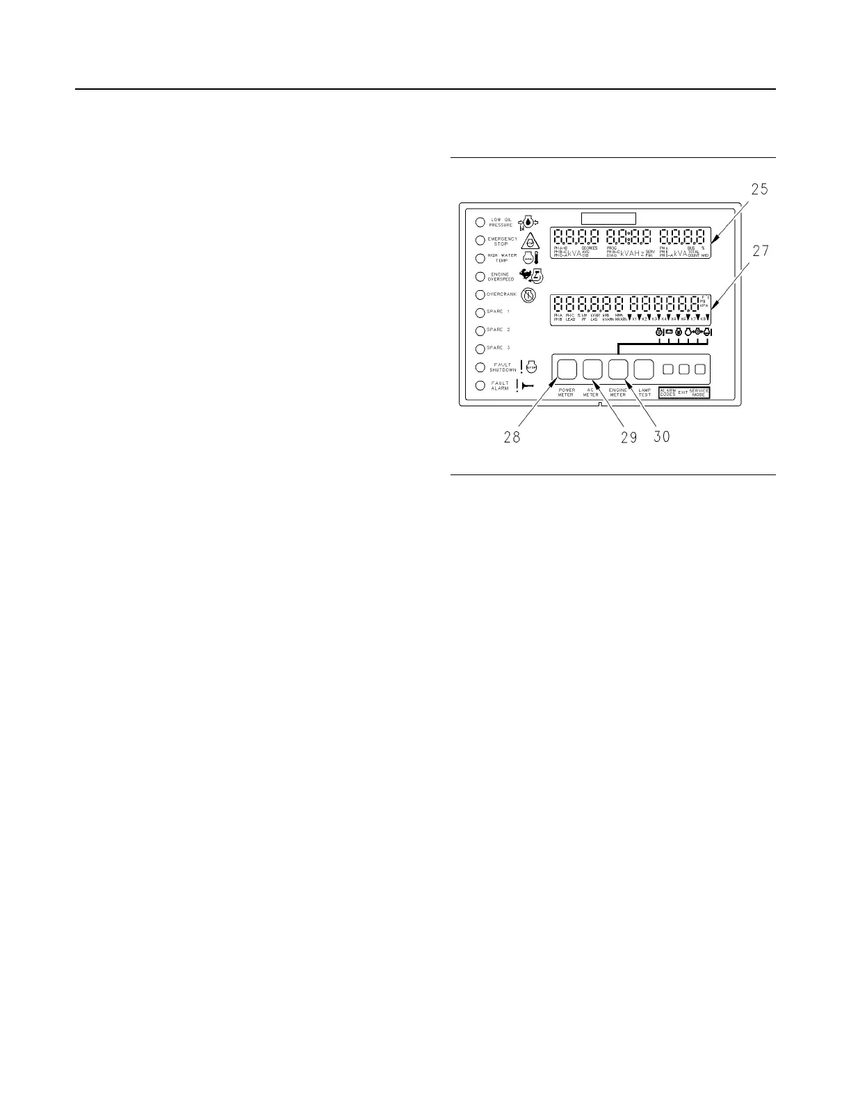
Display
Illustration 58 g00643442
Display Area of the GSC+
(25) Upper display
(27) Lower display
(28) The power meter key
(29) The AC meter key
(30) The engine meter key
The display consists of the upper display and the
lower display. Both displays are used for
programming functions when in service mode. For
more information, see Systems Operation, Testing
and Adjusting, RENR2484, “Electronic Modular
Control Panel II+ (EMCP II+)”.
Upper display
The upper display (25) shows: AC voltage, current
and frequency. Several options are available on the
upper display for AC metering. These options can be
viewed one at a time by pressing the AC meter key
(29) on the keypad. The options are listed below.
• Average voltage, generator frequency and total
current
• Line to line voltage, generator frequency and line
current for any one phase
• Line to line voltage for all three phases at once
• Line current for all three phases at once
Note: When total current increases above “9999A” ,
the GSC+ will show current in “kA” units.
• Line to neutral voltage for all three phases at once
SEBU7125-13
47
Operation Section
If Equipped
 Loading...