Keypad
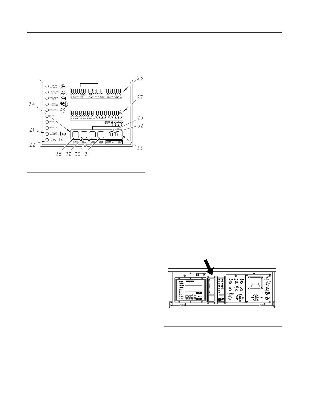
Illustration 59 g00643443
Keypad Area of the GSC+
(21) Fault shutdown indicator
(22) Fault alarm indicator
(25) Upper display
(26) Alarm codes key
(27) Lower display
(28) Power meter key
(29) AC meter key
(30) Engine meter key
(31) Lamp test key
(32) Exit key
(33) Service mode key
(34) Keypad
Keypad (34) is used to control the information that is
shown on the upper display (25) and lower display
(27). The seven keys have two sets of functions:
normal functions and service functions. For a
description of the service functions of the keys, see
the Systems Operation, Testing and Adjusting,
RENR2484, “Electronic Modular Control Panel II+
(EMCP II+)”. The normal functions of the keys are
described in the following paragraphs.
Power Meter Key (28) – This key controls the
viewing of power meter information. This information
is shown on the lower display. Pressing the key for at
least five seconds causes all the power meter data to
scroll once. The default power meter data then
resumes scrolling. If this key is pressed for less than
five seconds, the display will stop scrolling the power
meter functions until the key is pressed again.
AC Meter Key (29) – The AC meter key controls the
viewing of the AC parameters on the upper display.
Pressing the key causes the display to show a
different set of parameters.
Engine Meter Key (30) – This key controls the
viewing of engine parameters on the lower display.
Pressing the key stops the scrolling of engine
conditions. The value for one particular engine
condition will show continuously. The pointer flashes
indicating that the scrolling is stopped. The scrolling
of the engine conditions will resume when the engine
meter key is pressed again.
Lamp Test Key (31) – Pressing this key performs a
lamp test on the GSC+ and the optional alarm
module. On the GSC+, the ten fault indicators are ON
CONTINUOUSLY. Every segment of upper display
(5) and lower display (6) is ON. On the optional alarm
module, all of the indicators are ON and the horn
sounds. The lamp test function automatically turns off
if an operator presses the key and holds the key for
longer than ten seconds.
Alarm Codes Key (26) – If fault alarm indicator (22)
is FLASHING, pressing this key causes upper display
(25) to show the corresponding alarm fault code. If
this key is pressed again, the generator AC output
information will be shown on the upper display (25). If
fault alarm indicator (22) is OFF, this key has no
function.
Exit Key (32) – This key only functions when the
GSC+ is in Service Mode. For more information, see
the Systems Operation, Testing and Adjusting,
RENR2484, “Electronic Modular Control Panel II+
(EMCP II+)”.
Service Mode Key (33) – Pressing this key causes
the GSC+ to enter service mode. For more
information, see the Systems Operation, Testing and
Adjusting, RENR2484, “Electronic Modular Control
Panel II+ (EMCP II+)”.
Alarm Module
Illustration 60 g00635769
The Location of the Alarm Module (ALM) on the
EMCP II+ Control Panel
The alarm module (ALM) is optional. The ALM is
located in the center of the control panel. The
function of the alarm module is to provide a visual
and audible warning of engine conditions before
these conditions become severe enough that the
engine will shut down or will be unable to start.
SEBU7125-13
49
Operation Section
If Equipped
 Loading...