One basic alarm module is used to satisfy the
requirements for a standby NFPA 99 alarm module,
standby NFPA 110 alarm module, NFPA 99 remote
annunciator panel, and prime power alarm. This is
accomplished by using different inputs to the module
and different decals on the front of the module in
order to indicate alarms or shutdown conditions. For
all wiring and installation information, refer to the
Systems Operation, Testing and Adjusting,
RENR2484, “Electronic Modular Control Panel II+
(EMCP II+)”. Refer to the above manual for a listing
of indicators and alarm (horn) functions.
The front of the alarm module consists of the
following indicators.
• Four amber indicators, which can (depending on
module configuration) indicate High Coolant
Temperature, Low Coolant Temperature or Low
Coolant Level, Low Oil Pressure, Generator On
Load, Charger Malfunction, Low Oil Level and Low
Fuel Level
• Four red indicators, which can (depending on
module configuration) indicate a Not In AUTO
condition, Low DC Voltage, Air Damper Closed,
Low Oil Pressure Shutdown, Overcrank
Shutdown, High Coolant Temperature Shutdown,
and Overspeed Shutdown
• An audible alarm and Acknowledge/Silence switch
For more detailed information, refer to the Systems
Operation, Testing and Adjusting, RENR2484,
“Electronic Modular Control Panel II+ (EMCP II+)”.
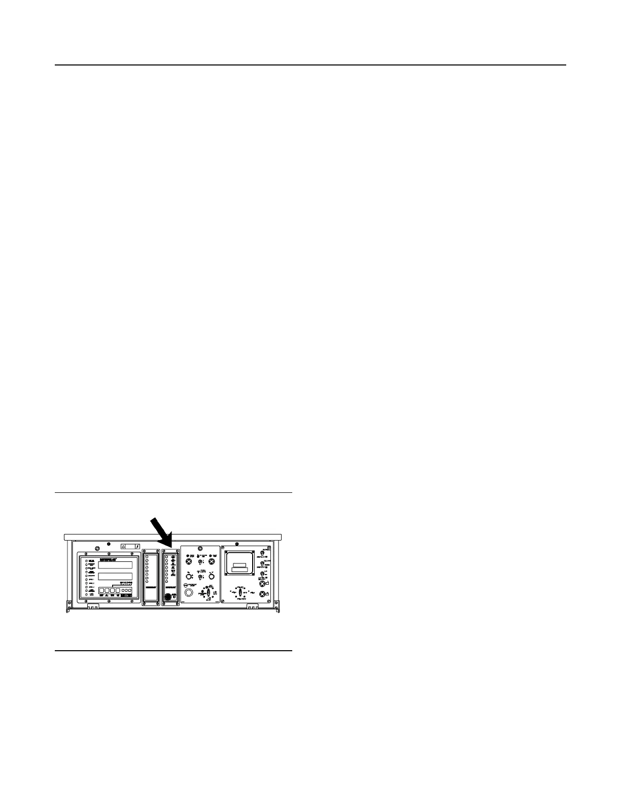
Custom Alarm Module
Illustration 61 g00635777
The Location of the Custom Alarm Module (CAM) on
the EMCP II+ Control Panel
The custom alarm module (CAM) is optional. The
CAM is located in the center of the control panel. The
function of the custom alarm module is to provide a
visual and audible warning of the conditions of the
customer supplied inputs before these conditions
become severe enough that the engine will shut
down or will be unable to start. The CAM is equipped
with a horn, alarm silence switch, a lamp test switch
and 8 switched inputs for customer use. For all wiring
and installation information, refer to the Systems
Operation, Testing and Adjusting, RENR2484,
“Electronic Modular Control Panel II+ (EMCP II+)”.
Refer to the above manual for the names of input
signals.
The front of the alarm module consists of the
following indicators.
• Four amber indicators, which are used to display
alarm conditions
50
SEBU7125-13
Operation Section
If Equipped
 Loading...