• Four red indicators, which are used to display
shutdown conditions
i05264058
Electronic Modular Control Panel
II+ with Paralleling (EMCP II+P)
(If Equipped)
SMCS Code: 4490
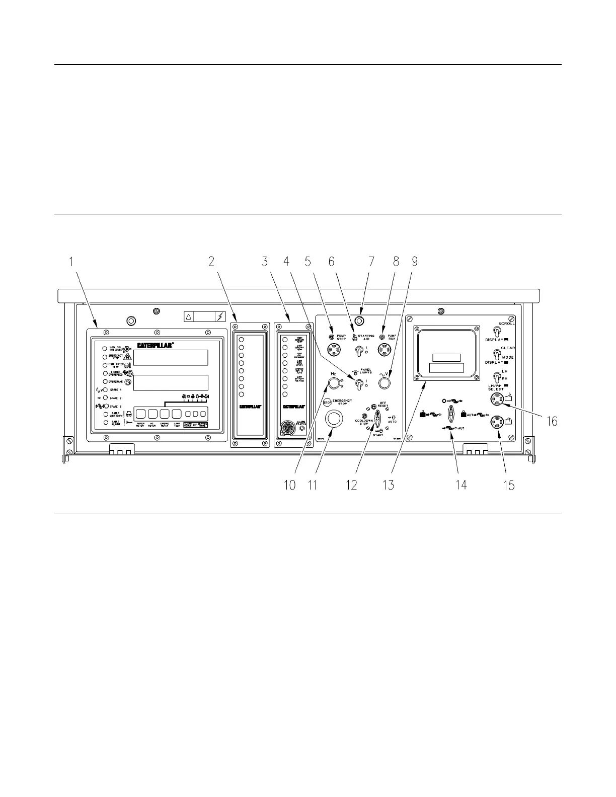
Illustration 62 g00639524
Electronic Modular Control Panel II+ With Paralleling (EMCP II+P)
(1) Generator set control + (GSC+)
(2) Alarm module (ALM) (optional)
(3) Custom alarm module (CAM)
(4) Panel light switch (PLS)
(5) Pump stop switch
(6) Start aid switch (SAS) (optional)
(7) Panel lights (PL)
(8) Pump run switch (optional)
(9) Voltage adjust rheostat (VAR)
(10) Speed potentiometer (SP) (optional) or
Governor switch (GS) (optional)
(11) Emergency stop push button (ESPB)
(12) Engine control switch (ECS)
(13) Cat Monitoring System
(14) Synchronization mode switch
(15) Breaker open pushbutton/indicator
(16) Breaker close pushbutton/indicator
The electronic modular control panel II+ with
paralleling (EMCP II+P) is located above the
generator distribution housing. The control panel
consists of a main panel with indicators, meters, and
control switches. This control panel may be equipped
with optional modules in order to match the needs
and requirements of the customer.
The left side of the control panel contains the
generator set control + (GSC+). This is the main
component of the system. The GSC+ displays
generator output, fault conditions and key engine
parameters. The center section of the control panel
may be blank, or contain one or two of the optional
alarm modules. The right side of the control panel
may be blank, or contain the Cat Monitoring System.
The main control panel may or may not contain all of
the components which are shown in Illustration 62 .
Some components are optional. The optional
components may not be required for your particular
application.
SEBU7125-13
51
Operation Section
Electronic Modular Control Panel II+ with Paralleling (EMCP II+P)
 Loading...