Illustration 63 g00692931
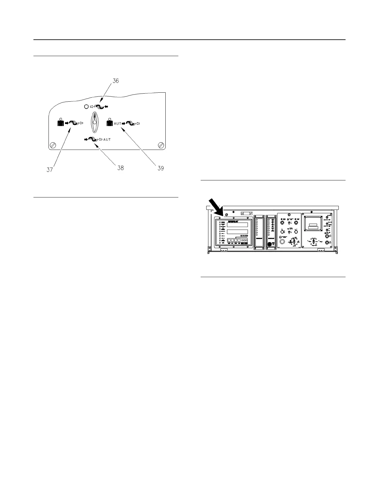
The Synchronization Mode Switch
(36) The OFF position
(37) The MANUAL (PERMISSIVE) position
(38) The AUTO position
(39) The SEMI-AUTO position
The AUTO position (6 o'clock) is used for complete
automatic paralleling. The EMCP II+P brings the
generator into sync with the bus and sends a signal
to close the motor operated breaker. The EMCP II+P
supports automatic paralleling to a dead bus.
Automatic voltage matching is not provided.
When the synchronizer mode switch is in the SEMI-
AUTO position (3 o'clock), the EMCP II+P brings the
generator into sync with the bus and holds it there
indefinitely. The operator brings the generator online
by manually closing the breaker. Automatic voltage
matching is not provided.
When the synchronizer mode switch is in the
MANUAL (PERMISSIVE) position (9 o'clock), the
operator adjusts the frequency and phase of the
generator in order to match the bus. When the
generator is in sync with the bus, the operator brings
the generator online by manually closing the breaker.
When the synchronizer mode switch is in the OFF
position (12 o'clock), all paralleling functions are
disabled.
Breaker Open Pushbutton/Indicator (15) – When
the generator is being taken off-line manually, the
breaker open pushbutton must be pressed by the
operator in order to open the breaker. When the
breaker is open and the engine is running, the
breaker open indicator (15) will light continuously.
Breaker Close Pushbutton/Indicator (16) – When
the generator is being paralleled semi-automatically
or manually, the breaker close pushbutton must be
pressed by the operator in order to close the breaker.
The system does not allow the breaker to close
unless in sync. When the breaker is closed
(generator is on line), the breaker close indicator (16)
will light continuously.
Below, you can find the descriptions of the following
main modules of the EMCP II+P:
• Generator Set Control + (GSC+)
• Alarm Module (ALM)
• Custom Alarm Module (CAM)
Generator Set Control + (GSC+)
Functions and Features of the GSC+
Illustration 64 g00634036
The Location of the GSC+ on the EMCP II+P Control
Panel
The left side of the control panel contains the
Generator Set Control + (GSC+). The GSC+ is the
main component of the system. The GSC+ displays
generator output, generator set functions, fault
conditions and key engine parameters. The GSC+
accepts information from the operator, magnetic
pickup, oil pressure sensor, water temperature
sensor and optional remote sources. This information
is used to determine the “ON/OFF” state of the
engine's air, fuel, and starter.
In the basic operating conditions, the GSC+ receives
a signal to run the generator set. The GSC+ turns on
the engine's fuel and starter. When the engine speed
reaches the crank termination speed, the starter is
disengaged. When the GSC+ receives a signal to
stop the engine, the GSC+ shuts off the fuel.
The functions of the GSC+ are listed below.
• The GSC+ controls the normal starting and
stopping of the engine.
SEBU7125-13
53
Operation Section
If Equipped
 Loading...