• The GSC+ shows engine conditions and
generator output information on two displays. The
displays also show fault codes and GSC+
programming information.
• The GSC+ monitors the system for faults. If a fault
occurs, the GSC+ performs a controlled fault
shutdown or provides a fault alarm annunciation.
The GSC+ uses indicators and displays in order to
describe the fault.
• The GSC+ contains programmable features for
certain applications or customer requirements.
The features of the GSC+ are listed below.
• Cycle Crank : The GSC+ can be programmed to
crank for adjustable time periods. For
programming instructions, refer to the Systems
Operation, Testing and Adjusting, RENR2484,
“Electronic Modular Control Panel II + (EMCP II
+)”.
• Governor Control : When the engine oil
pressure increases past the low oil pressure set
point, the GSC+ will indicate to the governor that
the governor should increase the engine speed
from idle RPM to rated RPM.
• Cooldown : Upon receiving a signal to perform a
normal shutdown, the GSC+ will wait a
preprogrammed amount of time before shutting
the engine down with the fuel control.
• Automatic Operation : While in the automatic
mode, the GSC+ can be started by a remote
initiate signal (contact closure). Upon loss of the
signal (contact opening), the GSC+ will perform a
normal shutdown.
• Alarm Module Communication : The GSC+ can
transmit fault and alarm conditions to an alarm
module (AM).
• Power Down : The EMCP II+P system is
designed to remove power from the GSC+ when
the engine control switch (ECS) is in the OFF/
RESET mode and when the proper jumper wire is
removed. The GSC+ will not power down until the
crank termination relay and the fuel control relay
are both off for about 70 seconds. If the wire is not
removed, the GSC+ will remain powered up. For
the wiring diagram and the location of the jumper
wire, refer to the Systems Operation, Testing and
Adjusting, RENR2484, “Electronic Modular
Control Panel II + (EMCP II+)”.
• Fuel Solenoid Type : The GSC+ can be
programmed to work with either an energized to
run (ETR) fuel system or an energized to shut
down (ETS) fuel system.
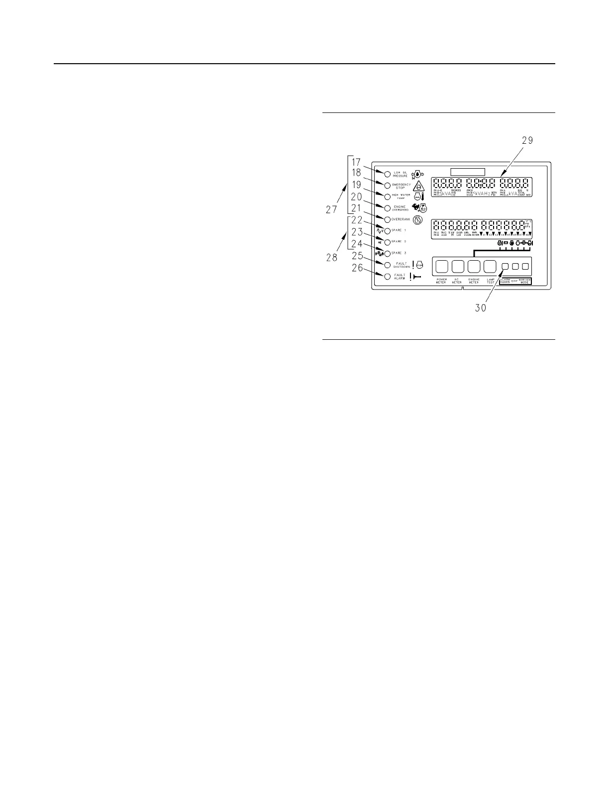
Fault indicators
Illustration 65 g00634142
Display Area of the GSC+
(17) Low oil pressure indicator
(18) Emergency stop indicator
(19) High water temperature indicator
(20) Engine overspeed indicator
(21) Overcrank indicator
(22) Spare 1 indicator/Voltage match
(23) Spare 2 indicator/Frequency match
(24) Spare 3 indicator/Phasing match
(25) Fault shutdown indicator
(26) Fault alarm indicator
(27) Dedicated shutdown indicators
(28) Spare fault indicators
(29) Upper display
(30) The alarm codes key
The ten fault indicators are used in order to show and
describe a fault that is present. The fault indicators
are divided into four groups. The four groups are
listed below.
• fault alarm indicator (26)
• fault shutdown indicator (25)
• spare fault indicators (28)
• dedicated shutdown indicators (27)
54
SEBU7125-13
Operation Section
If Equipped
 Loading...