For more detailed information, refer to the Systems
Operation, Testing and Adjusting, RENR2484,
“Electronic Modular Control Panel II+ (EMCP II+)”.
Custom Alarm Module
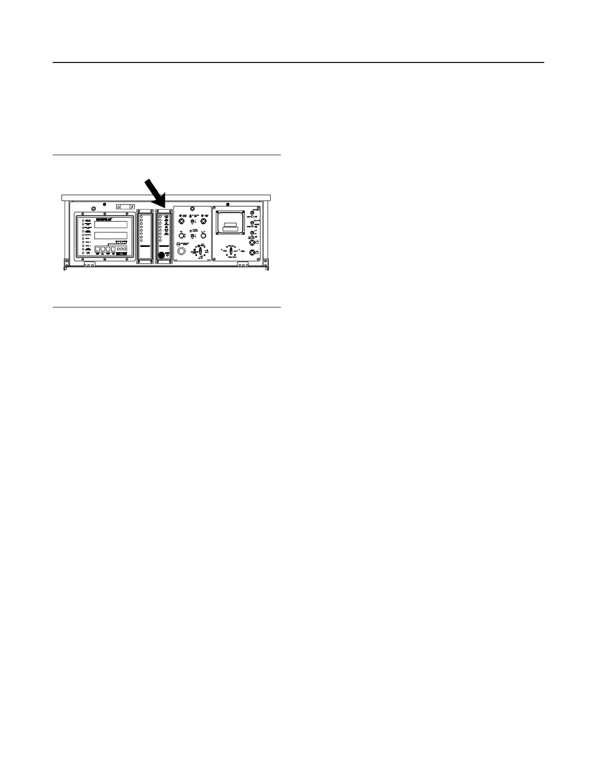
Illustration 69 g00635777
The Location of the Custom Alarm Module (CAM) on
the EMCP II+P Control Panel
The Custom Alarm Module (CAM) is located in the
center of the control panel. The function of the
custom alarm module is to provide a visual and
audible warning of the conditions of the customer
supplied inputs before these conditions become
severe enough that the engine will shut down or will
be unable to start. The CAM has eight indicators, an
audible horn, acknowledge/silence switch, and the
lamp test switch. Four of the indicator lamps are
yellow. These yellow indicator lamps are used to
indicate a fault shutdown. For all wiring and
installation information, refer to the Systems
Operation, Testing and Adjusting, RENR2484,
“Electronic Modular Control Panel II+ (EMCP II+)”.
Refer to the above manual for the names of input
signals.
Note: If an optional alarm module is ordered, the
audible horn, acknowledge/silence switch, and lamp
test switch will come standard with the optional alarm
module.
The front of the alarm module consists of the
following indicators.
• Four amber indicators, which are used to display
alarm conditions
SEBU7125-13
59
Operation Section
If Equipped
 Loading...