Keypad (38) is used to control the information that is
shown on upper display (29) and lower display (31).
The seven keys have two sets of functions: normal
functions and service functions. For a description of
the service functions of the keys, see the Systems
Operation, Testing and Adjusting, RENR2484,
“Electronic Modular Control Panel II+ (EMCP II+)”.
The normal functions of the keys are described in the
following paragraphs.
Alarm Codes Key (30) – If fault alarm indicator (26)
is FLASHING, pressing this key causes the upper
display (29) to show the corresponding alarm fault
code. If this key is pressed again, the generator AC
output information will be shown on the upper display
(29). If fault alarm indicator (26) is OFF, this key has
no function.
Power Meter Key (32) – This key controls the
viewing of power meter information. This information
is shown on the lower display. Pressing the key for at
least five seconds causes all the power meter data to
scroll once. The default power meter data then
resumes scrolling. If this key is pressed for less than
5 seconds, the display will stop scrolling the power
meter functions until the key is pressed again.
AC Meter Key (33) – The AC meter key controls the
viewing of the AC parameters on the upper display.
Pressing the key causes the display to show a
different set of parameters.
Engine Meter Key (34) – This key controls the
viewing of engine parameters on the lower display.
Pressing the key stops the scrolling of engine
conditions. The value for one particular engine
condition will show continuously. The pointer flashes
indicating that the scrolling is stopped. The scrolling
of the engine conditions will resume when the engine
meter key is pressed again.
Lamp Test Key (35) – Pressing this key performs a
lamp test on the GSC+ and the optional alarm
module. On the GSC+, the ten fault indicators are ON
CONTINUOUSLY. Every segment of upper display
(5) and lower display (6) is ON. On the optional alarm
module, all of the indicators are ON and the horn
sounds. The lamp test function automatically turns off
if an operator presses the key and holds the key for
longer than 10 seconds.
Exit Key (36) – This key only functions when the
GSC+ is in Service Mode. For more information, see
the Systems Operation, Testing and Adjusting,
RENR2484, “Electronic Modular Control Panel II+
(EMCP II+)”.
Service Mode Key (37) – Pressing this key causes
the GSC+ to enter service mode. For more
information, see the Systems Operation, Testing and
Adjusting, RENR2484, “Electronic Modular Control
Panel II+ (EMCP II+)”.
Alarm Module
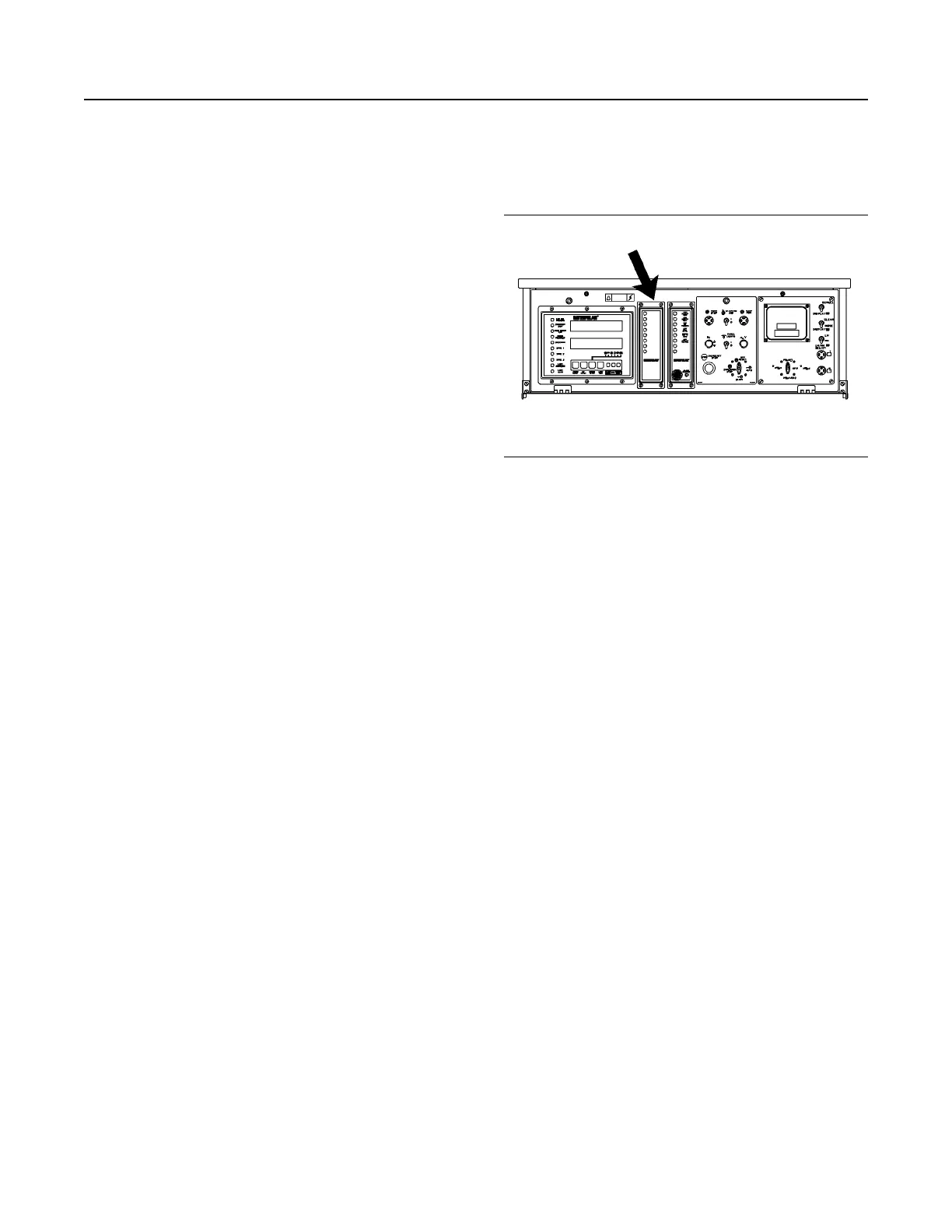
Illustration 68 g00635769
The Location of the Alarm Module (ALM) on the
EMCP II+P Control Panel
The alarm module (ALM) is optional. The ALM is
located in the center of the control panel. The
function of the alarm module is to provide a visual
and audible warning of engine conditions before
these conditions become severe enough that the
engine will shut down or will be unable to start.
One basic alarm module is used to satisfy the
requirements for a standby NFPA 99 alarm module,
standby NFPA 110 alarm module, NFPA 99 remote
annunciator panel, and prime power alarm. This is
accomplished by using different inputs to the module
and different decals on the front of the module in
order to indicate alarms or shutdown conditions. For
all wiring and installation information, refer to the
Systems Operation, Testing and Adjusting,
RENR2484, “Electronic Modular Control Panel II+
(EMCP II+)”. Refer to the above manual for a listing
of indicators and alarm (horn) functions.
The front of the alarm module consists of the
following indicators.
• Four amber indicators, which can (depending on
module configuration) indicate High Coolant
Temperature, Low Coolant Temperature or Low
Coolant Level, Low Oil Pressure, Generator On
Load, Charger Malfunction, Low Oil Level, and
Low Fuel Level
• Four red indicators, which can (depending on
module configuration) indicate a Not In AUTO
condition, Low DC Voltage, Air Damper Closed,
Low Oil Pressure Shutdown, Overcrank
Shutdown, High Coolant Temperature Shutdown,
and Overspeed Shutdown
• An audible alarm and Acknowledge/Silence switch
58
SEBU7125-13
Operation Section
If Equipped
 Loading...