Digital Inputs
There are several digital inputs and outputs on
“EMCP 4.1” and “EMCP 4.2” . For detailed
information about the inputs on this electronic control
module, see Systems Operation, Troubleshooting,
Testing, and Adjusting, UENR1209, “EMCP4.1/4.2”.
Control Panel
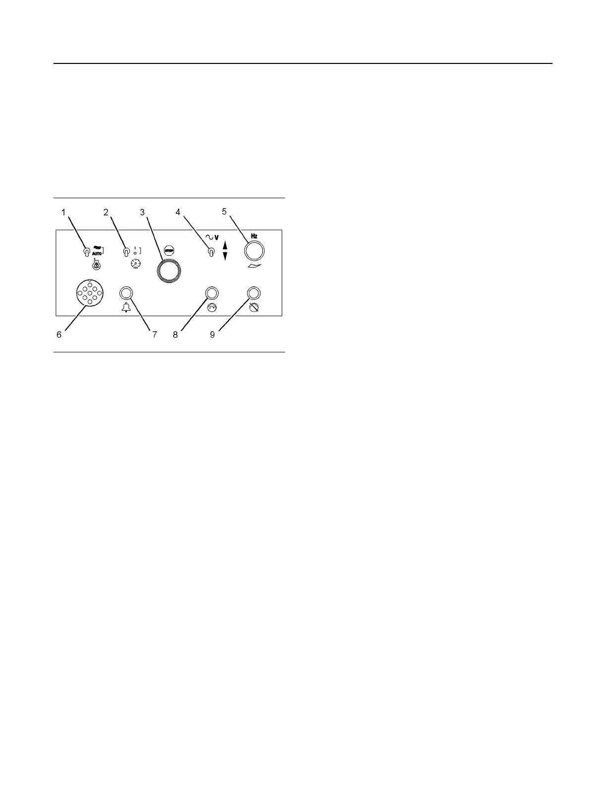
Illustration 74 g01185966
(1) Starting aid auto/manual switch (if equipped)
(2) Panel light switch
(3) Emergency stop push button
(4) Voltage adjust switch (if equipped)
(5) Speed potentiometer (if equipped)
(6) Customer connection (if equipped)
(7) Horn (if equipped)
(8) Pump run switch (if equipped)
(9) Pump stop switch (if equipped)
Starting Aid Auto/Manual Switch (1) – The starting
aid switch is optional. The starting aid switch is used
to inject ether into the engine when you are starting
the engine in cold-weather conditions. When the
starting aid switch is in the ON position, the solenoid
valve is energized. The switch then meters a specific
amount of ether into a holding chamber. When the
starting aid switch is released, the solenoid releases
the ether to the engine.
Panel Light Switch (2) – The panel lights switch
turns on or the panel lights switch turns off the panel
lights.
Emergency Stop Push Button (3) – The emergency
stop push button (ESPB) is used to shut down the
engine during an emergency situation. If equipped,
the ESPB shuts off the fuel and the ESPB activates
the optional air shutoff.
Voltage Adjust Switch (4) – This switch can be used
to raise the voltage. The switch can also be used to
lower the voltage.
Speed Potentiometer (5) – The speed
potentiometer is optional. The speed potentiometer
can be used with the generator set that has an
electronic governor.
Customer Connection (6) – The customer
connection is a 9-pin connector for connecting the
Cat Electronic Technician.
Horn (7) – The horn provides an audible alarm.
Pump Run Switch (if equipped)(8) – Under normal
circumstances, the fuel transfer process is automatic.
In some instances, a manual operation may be
required. Press the pump run switch once in order to
start the pump manually.
Pump Stop Switch (if equipped)(9) – The pump
stop switch is a push-button switch that locks into
position. The pump stop switch will stop the pump if
the switch is locked into position. Releasing the
switch will place the pump back into the run mode.
SEBU7125-13
67
Operation Section
EMCP 4.1/4.2 If equipped
 Loading...