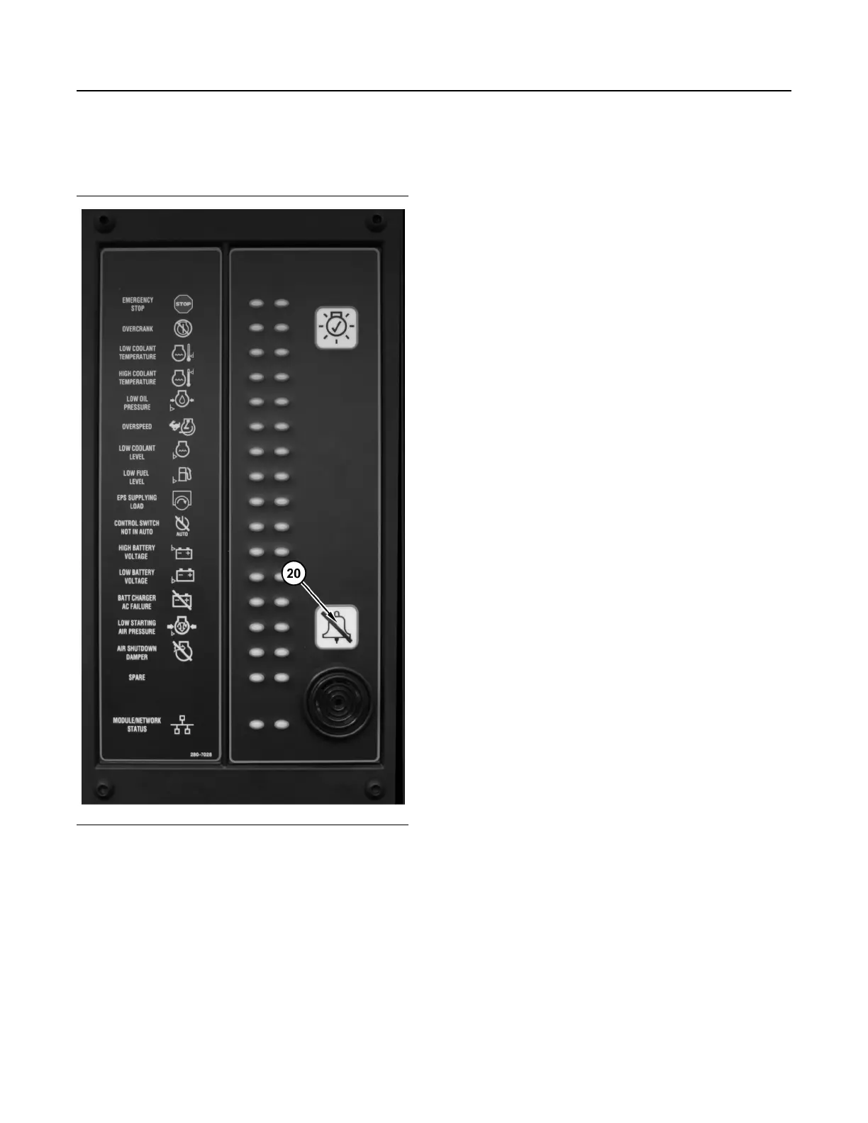
Annunciator Module
Illustration 75 g02111119
(20) Alarm acknowledge button
General Information
The annunciator module is used to indicate various
system events and conditions. The annunciator
module uses indicator lights and an audible horn to
give the operator information about the status of the
system. The annunciator module can be used to
announce faults and/or status signals to the operator.
The annunciator module allows the operator to
silence the horn. The annunciator module also allows
the operator to acknowledge faults to the system.
There are 17 pairs of LED indicators on the front
panel of the annunciator. The 16 pairs of LED
indicators are used to announce events, diagnostics,
and ready signals. The 17th pair of LED indicators is
used as a combined network/module status LED.
The 17th pair of LED indicators can tell the operator if
there is a problem with the J1939 data link
connection.
Basic Operation
Each pair of LED indicators on the annunciator
consists of two of the following three colors: green,
yellow and red. For example, a pair of red and yellow
LED indicators may be configured for engine oil
pressure. If a low engine oil pressure warning is read
over the data link, the annunciator will flash the
yellow LED. The audible horn will then sound. If the
low engine oil pressure shutdown is read over the
data link, the annunciator will flash the red LED. The
audible horn will then sound.
To acknowledge the shutdown and alarm conditions
or to silence the horn, press the “Alarm
Acknowledge” button (20).
To test the LED indicators or the horn when the data
link is either connected or disconnected, hold the
“Lamp Test” button in.
Configuration
The annunciator module can be customized in order
to signal many different conditions that are related to
the system. Each pair of LEDs must be configured by
using the appropriate service tool. Once the service
tool has been connected to the annunciator, the user
must enter the “Configuration” screen. Each pair of
LEDs has four settings: SPN, Trigger Type, Trigger
Severity Level and Failure Mode Identifier (FMI).
68
SEBU7125-13
Operation Section
EMCP 4.1/4.2 If equipped
 Loading...