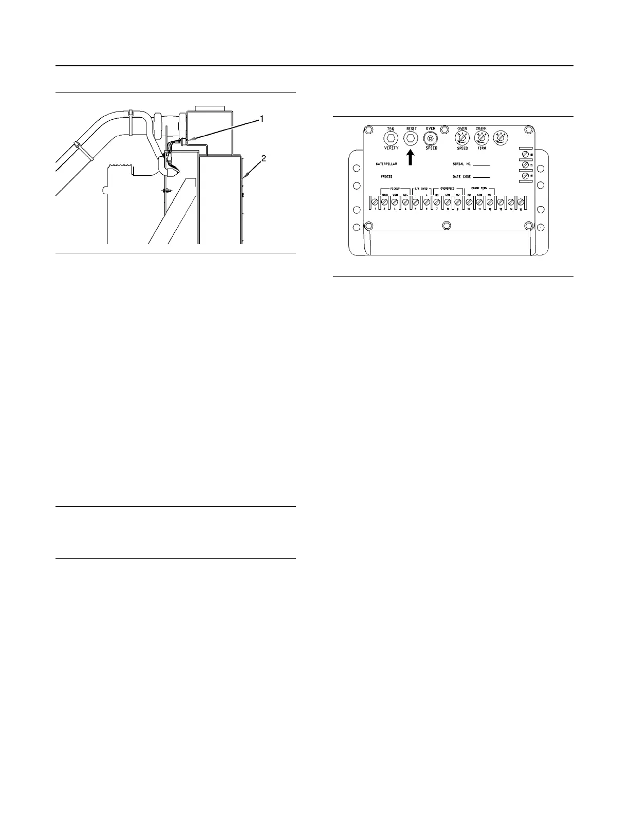
Illustration 80 g01009211
(1) Typical coolant loss sensor
(2) Radiator
If the coolant drops below the minimum level, the
sensor may sound an alarm, or the sensor may
cause a shutoff to avoid engine overheating or
possible engine damage. Coolant must be added to
the radiator or the expansion tank in order to reset
the condition.
Testing the Shutoff and Alarm
System
Most control panels are equipped with a lamp test
switch. Turn the switch to the ON position in order to
check the indicator lights for proper operation.
Replace worn bulbs immediately.
The shutoffs and alarms should be tested every 1000
service hours or twice a year for proper operation by
authorized, experienced service personnel.
NOTICE
During testing, abnormal operating conditions must
be simulated. Perform the tests correctly in order to
help prevent possible engine damage.
Refer to the Service Manual for more information on
testing procedures or consult your Caterpillar dealer.
Testing of the Overspeed Switch
Illustration 81 g00291056
Electronic Overspeed Switch
The overspeed shutoff switch is located in the
junction box. The overspeed shutoff switch must be
reset before you can restart the engine. To reset the
switch, push the “RESET” button. The button will
remain in this position unless an overspeed condition
occurs.
The Electronic Overspeed Switch with Cranking
Termination has a 75 percent “VERIFY” button, a
“RESET” button, and an “OVERSPEED” indicator
lamp.
The Electronic Overspeed Shutoff Switch with
Cranking Termination has a sensing circuit which
prevents the starter pinion from remaining engaged
in the flywheel at excessive rpm. Crank Termination
has an adjustable engine speed setting. This signals
the starter motor when the engine is firing and
cranking must be terminated. Once the speed setting
is reached, a switch opens. This will start the engine
hour meter.
Once the starting motor cranks the engine, the pinion
gear can remain engaged with the flywheel as the
engine speed increases. The magnetic pickup opens
the circuit to the starting motor at 400 rpm. This will
allow the pinion gear to disengage.
The circuit will remain open until the flywheel stops.
This prevents energizing the starting motor circuit
again while the flywheel is turning.
The engine may be equipped with either an
Overspeed Shutoff Switch or an Electronic
Overspeed Switch with Cranking Termination. Both
switches can be checked for proper operation at 75
percent of overspeed condition. Use the following
procedure:
1. Determine full load speed (rpm) from the Engine
Information Plate.
2. Operate the engine at the corresponding speed
(rpm) that is shown for the engine. Refer to table 3
.
72
SEBU7125-13
Operation Section
Engine Shutoffs and Engine Alarms
 Loading...