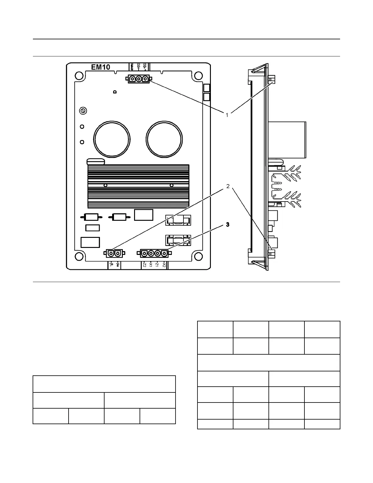
Illustration 89 g03844853
Excitation Module 10 (EM10)
(1) Connector P3 (2) Connector P2 (3) Connector P4
EMCP IVR Connection
To regulate the generator terminal voltage, the EMCP
communicates the desired excitation command to the
excitation module through a pulse width modulation
(PWM) signal. A twisted pair of shielded cable must
be used for the communication link. Table 5 details
the connections to be made between the EMCP and
Excitation Module.
Table 5
EMCP 4.1 and EMCP 4.2 Connections to Excitation Module
(70-pin connector)
EMCP 4.1 and EMCP 4.2 70-
Pin Connector
Excitation Module 3-Pin
Connector
Digital Output
#2 / IVR CS+
68 CS+ P3-2
(continued)
(Table 5, contd)
Battery nega-
tive splice
60 or 65 CS- P3-3
Battery nega-
tive splice
60 or 65 Shield P3-1
EMCP 4.3 and EMCP 4.4 Connections to Excitation Module
(120-pin connector)
EMCP 4.3 and EMCP 4.4 120-
Pin Connector
Excitation Module 3-Pin
Connector
PWM Output
#2 Positive
28 CS+ P3-2
PWM Output
#2 Negative
8 CS- P3-3
Shield 19 Shield P3-1
SEBU7125-13
81
Operation Section
Voltage Regulators
 Loading...