Table 6 provides information on the technical
specification of the EM10 and EM15 modules.
Selection of the appropriate module must be
determined by the following:
• Nominal and maximum generator excitation
current at full load (standby 0.8 PF).
• The maximum AC voltage input.
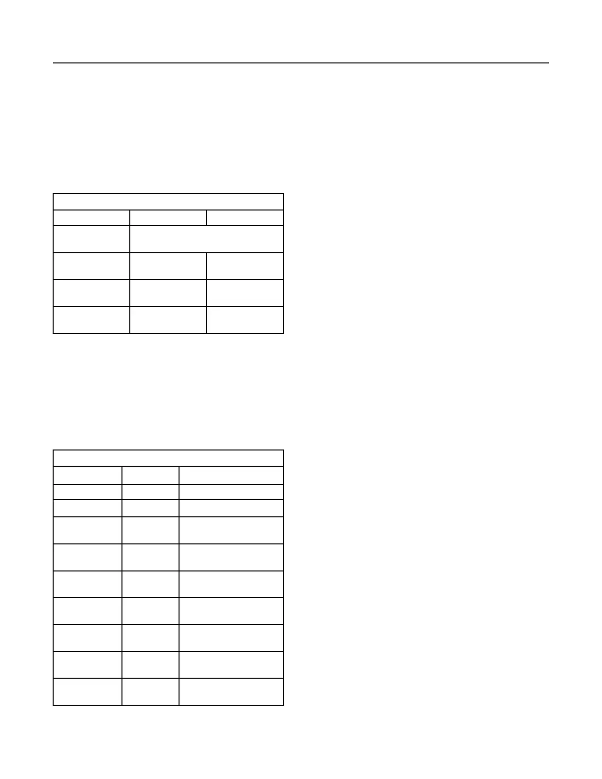
Table 6
EM10 and EM15 Technical Specifications
EM10 EM15
Compatible Genera-
tor Excitation Types
Permanent Magnet (PM) Self-Excitation
(SE) Internal Excitation (IE/AREP)
(1)
Nominal Field Cur-
rent Output
6A 7A
Maximum (forcing)
Field Current Output
10A 15A
Maximum AC Volt-
age Input
180Vms 240Vms
(1)
Internal Excitation (IE is also referred to as “Auxiliary Regula-
tion Excitation Principle”(AREP)
IVR Excitation Module Connections
The EM10 and EM15 excitation modules have three
plug type multiple-pin connectors. The connectors
are labeled P2, P3, and P4 as shown in illustration 89
. Table 7 describes the signal and function of each
connector pin.
Table 7
Excitation Module Connections
Terminal Label Signal/Function
P2-1 F+ Exciter Field Positive
P2-2 F- Exciter Field Negative
P3-1 Shield Excitation Command Control
Signal Shield
P3-2 CS+ Excitation Command Control
Signal Positive
P3-3 CS- Excitation Command Control
Signal Negative
P4-1 X2 Excitation Power Supply In-
put X2
P4-2 Z1 Excitation Power Supply In-
put Z1
P4-3 X1 Excitation Power Supply In-
put X1
P4-4 Z2 Excitation Power Supply In-
put Z2
Note: The X2 and Z1 connections are internally
linked within the excitation module. The link provides
a point of common connection for the auxiliary
windings where an AREP or IE excitation supply is
available. Also, the X2 and Z1 connections may be
linked externally to the excitation module. Only three
connections (X1, X2, and Z2) are needed for the EM.
Refer to Systems Operation/Test and Adjust/
Troubleshooting, UENR1209, “Integrated Voltage
Regulator Connections” for excitation module wiring
connections. The wiring diagrams are for self-
excitation (shunt), auxiliary windings (AREP/IE), and
permanent magnet (PM) configurations.
The voltage regulator knee frequency must be
configured for your specific package requirements.
The knee frequency for 50 Hz operation will usually
be between 48.0 and 49.8 Hz. For 60 Hz operation,
the parameter must be set between 58.0 to 59.8 Hz.
Refer to Illustration 88 for an example under-
frequency roll-off (loading) profile.
82
SEBU7125-13
Operation Section
Voltage Regulators
 Loading...