12
Control Panel – Service
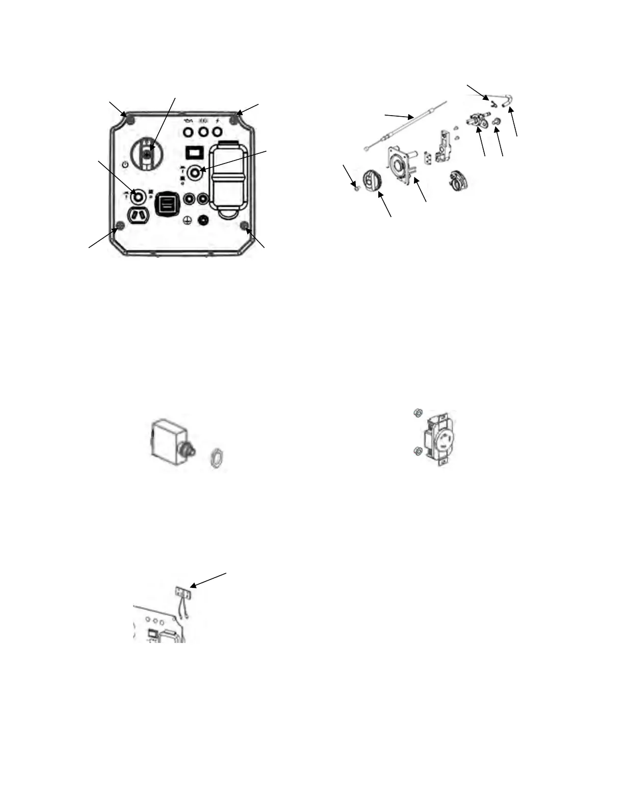
Remove the four bolts (1). Remove generator
switch screw (2) and pull the generator switch
forward. Remove both circuit breaker nuts (3) by
twisting off. Pull the control panel cover forward
and up slowly. Make sure that the cables move
freely and are not damaged. Tag the wires to
identify them and then disconnect the wiring
harnesses. Remove the front cover and place on
a surface that will protect the panel from
damage.
Circuit Breakers:
Each circuit breaker is held to the panel with a
half nut located on the front of the panel. Tag the
wires to identify them and then disconnect the
circuit breaker. Remove the half nut from the
front of the panel then remove the circuit breaker
from the rear of the panel.
Display LEDs:
The Display LEDs (1) are held to the panel with
a bracket that mounts to the panel from the rear.
Disconnect the harness from the plug and
remove the bracket. Remove the Display LEDs
from the bracket.
Generator Switch:
The generator switch is held to the panel with a
screw (1). Remove the screw and remove the
knob (8) from the front of the panel. The choke
rod (2) is attached to the generator switch from
the rear of the panel. The fuel line (4) is attached
with a collar (3) to the rear of the fuel assembly
(6), attached to the rear of the generator switch
with a bolt (5). Remove the generator switch (7)
from the rear of the panel once all is
disconnected.
Receptacles and Covers:
Each receptacle (GFCI, DC, and USB) is held to
the panel with two nuts. Tag the wires to identify
them and remove the wires from the receptacle.
Remove the nuts, and then remove the
receptacle from the rear of the panel. The
receptacle cover can then be removed from the
front of the panel.
Ground Terminal:
The ground terminal (1) is held to the panel with
a double nut located on the front of the panel.
Remove the double nut from the front of the
panel then remove the ground terminal from the
rear of the panel
 Loading...