17
Remove any carbon deposits from the valve
seats. Use a runout gauge to measure the
concentricity of the seat. Alternatively, apply a
light coat of a marking compound to the valve
face and insert the valve into the head. Press
the valve in firmly and then remove the valve.
Check the paint for signs that the valve seat is
not concentric. Remove the marking compound
from both surfaces.
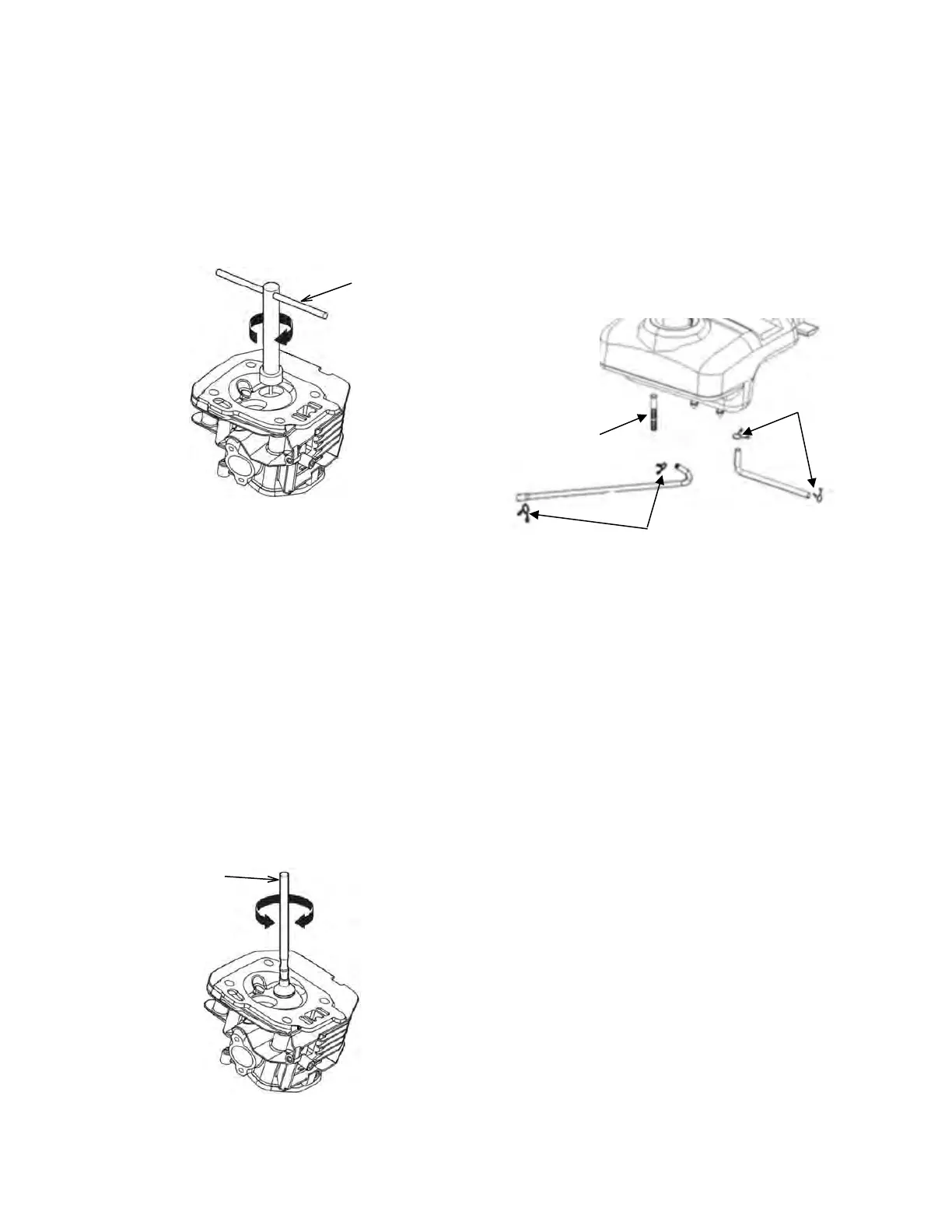
If the marking compound shows that the valve
seat is not concentric, use a 45° valve seat
cutter (1) to produce a smooth, concentric seat.
Always turn the cutter clockwise. Use both the
45° valve seat cutter and the 32° valve seat
cutter to adjust the valve seat so that it contacts
the middle of the valve face. The 32° valve seat
cutter removes material from the top of the seat.
The 45° valve seat cutter removes material from
the bottom of the seat. Be sure that when
finished the area where the valve contacts the
valve seat is from 3.3 to 3.7mm wide. To
complete the procedure, make a light pass with
the 45° valve seat cutter to remove any burrs
that may be on the edge of the seat. When
complete, use the marking compound to check
for concentricity. Make sure that there is good
contact all the way around the valve.
Apply lapping compound to the valve face and
insert the valve into the cylinder head. Use a
valve lapping tool (1) to finish surfacing the valve
and valve seat. Remove any remaining
compounds before assembling the cylinder
head. Make sure that the pushrods are firmly
seated in the lifters. After assembly, follow the
Engine Valve Lash – Adjust and the Cylinder
Pressure – Check procedures to ensure a
proper assembly.
Fuel Line and Filter – Replace
Drain the fuel from the fuel tank into an
appropriate container. Start the engine and let
the engine run out of fuel. Turn the generator
switch to the off “0” position.
Remove the side panel (side with service access
doors) by removing the 2 bolts and lifting out
and away (be careful to avoid breaking the
locating tabs). The fuel tank does not need to be
removed to replace the fuel line. Move clamps
(1) to the center of the fuel line.
Remove the fuel line from the fuel filter (2).
Remove the fuel filter. Wipe the mounting
surface with a clean rag and install a new fuel
filter. Tighten the fuel filter.
Remove the fuel line from the rear of the
generator switch and the carburetor.
Inspect the clamps. If the clamps are damaged
discard the old clamps and use new clamps.
Place two clamps near the center of each new
fuel line and install the fuel lines. Position the
clamps so that they will hold the fuel line
securely in place.
 Loading...