11
Connectors and Pin Assignments
12
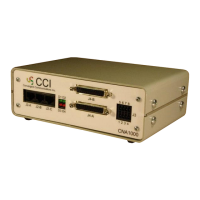
802.3 Ethernet 10/100base-T Communications
Ethernet network communications is available on the rear panel on port
J5, RJ-45 connection.
Ethernet network connector J5 pin assignments are provided in Table-3
below.
Pin Function
1 E_TX+
2 E_TX-
3 E_RX+
4 - -
5 - -
6 E_RX-
7 - -
8 - -
Table-3: Ethernet RJ45 Connector Pin Assignments
Figure-5: Ethernet Network Connector J-5
as viewed on the Rear Panel
Pin Function
1 OUT1 +
2 OUT1 -
3 OUT2 +
4 OUT2 -
5 IN1 +
6 IN1 -
7 IN2 +
8 IN2 -
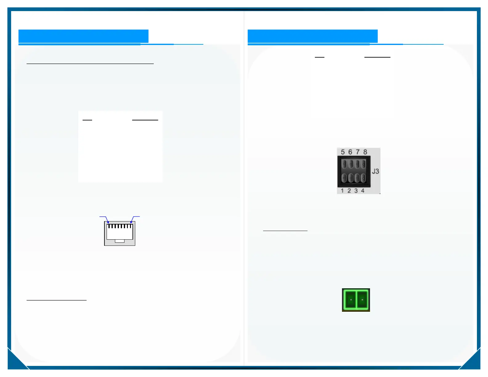
Table-4: I / O Connector J-3 Pin Assignments
Figure-6: I / O Connector J-3 as Viewed on the Front Panel
Optically Isolated I / O
The CNA1000 has two each optically isolated Inputs and two each
optically isolated Outputs available on connector J-3 shown in Figure-6.
Pin assignments for the I / O connector are provided in Table-4.
DC Input Supply
The CNA1000 operates on 9 to 18 VDC input and is DC isolated to a
minimum of 2000 VRMS.
The pin assignment for DC supply input is shown in Figure-7 below.
+ -
Figure-7: DC Power Input Connector J-1
as viewed on the rear panel
Connectors and Pin Assignments
 Loading...