FORCECLIMA 12600 SOUNDLESS HEATING FORCECLIMA 12600 SOUNDLESS HEATING
6362
ENGLISH ENGLISH
7. Sleep mode
8. Oscillation
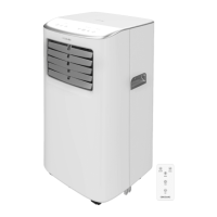
Remote control Fig. 5
1.
2. Timer
3. Oscillation
4. Sleep mode
5. Increase/decrease
6. Modes
7. Fan speed
8. Unit switch:
NOTE:
The graphics in this manual are schematic representations and may not exactly match the
product.
2. BEFORE USE
- This appliance is packaged in a way as to protect it during transport. Take the appliance
out of its box and remove all packaging materials. You can keep the original box and other
packaging elements in a safe place. This will help you prevent product damage when
transporting it in the future. In case the original packaging is disposed of, make sure all
packaging materials are recycled accordingly.
- Make sure all parts and components are included and in good conditions. If there is any
immediately.
Box contents
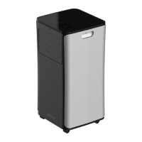
- ForceClima 12600 SoundLess Heating portable air conditioner
- Window kit
- Remote control
- Instruction manual
3. PRODUCT INSTALLATION
NOTE:
- Leave a minimum of 50 cm distance to walls and other objects. Fig. 6
- Do not install and use the air conditioning in the bathroom or other humid environments.
- Before using the portable air conditioner, keep it upright for at least two hours. When
similar) sin la previa autorización de CECOTEC INNOVACIONES, S.L.
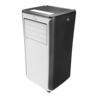
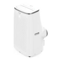
1. PARTS AND COMPONENTS
Fig. 1
1. Control panel
2. Front housing
3. Wheels
4. Top cover
5. Air outlet/louvers
6. Back housing
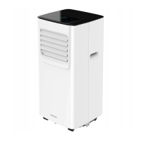
Fig. 2
1.
2. Back housing
3. Air outlet
4. Drainage hole
5. Handle
6. Cable holder
7. Continuous-drainage hole
8.
9. Cord
10. Plug
Fig. 3
1. Air outlet pipe
2. Window sealing plate
Control panel. Fig. 4
1.
2. Modes
3. Fan speed
4. Decrease icon
5. Increase icon
6. Timer