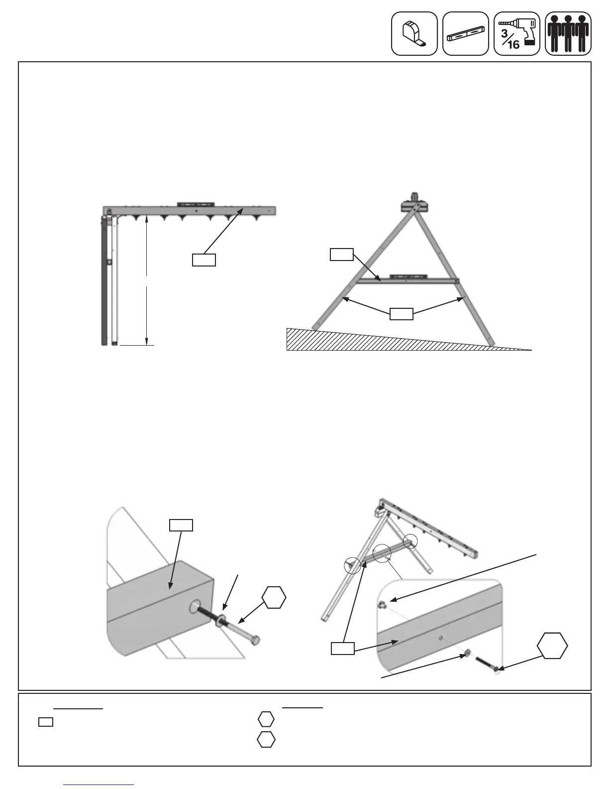
Step 29: Attach Cross Support
Hardware
Wood Parts
Pre-drill all holes using a 3/16” drill bit before installing the lag screws.
A:Checktomakesurethe(270)EngineeredSWBeamislevelandthebottomofthebeamtotheground
measures85”.(g.29.1)
B:Toadjustforunevenground,raiseorlowerthe(290)SupportCrossonthe(282)SWPost.Makesurethe
SupportCrossislevelpriortoattachingwiththelagscrews.(g.29.2)
Fig. 38.1
2 x 5/16 x 4-3/4” Lag Screw
(5/16” at washer)
1 x 5/16 x 2-3/8” Wafer Bolt
(5/16” at washer, 5/16” t-nut)
WB8
LS9
1 x Support Cross FSC 2-1/2 x 3 x 64”
290
360
C:Place(290)SupportCrossbetween(282)SWPostatthepreviouslydeterminedspotandfastenwith1
(LS9)5/16x4-3/4”LagScrew(withatwasher)perside.(g.29.3and29.4)Notice one side is fastened on
the outside and one on the inside. It is important that each side is positioned exactly the same as the
diagram. (g. 29.3) Tighten the lag screw when you are sure (290) Support Cross is level.
D:Attach1(WB8)5/16x2-3/8”WaferBolt(withatwasherandt-nut)to(290)SupportCrossthroughthe
middlehole.(g.29.3)IMPORTANT! MAKE SURE THE BOLT IS ATTACHED TO MINIMIZE CHECKING OF
WOOD.
85"
5/16”T-Nut
Fig. 29.1
290
Fig. 29.2
Fig. 29.4
Fig. 29.3
5/16”Flat
Washer
5/16”Flat
Washer
LS9
290
270
290
282
WB8
104 support@cedarsummitplay.com
 Loading...