Fig. 4.6
8 x 1/4 x 2-1/2” Wafer Lag
Hardware
WL5
Fig. 4.7
Top
Bottom
040
030
WL5
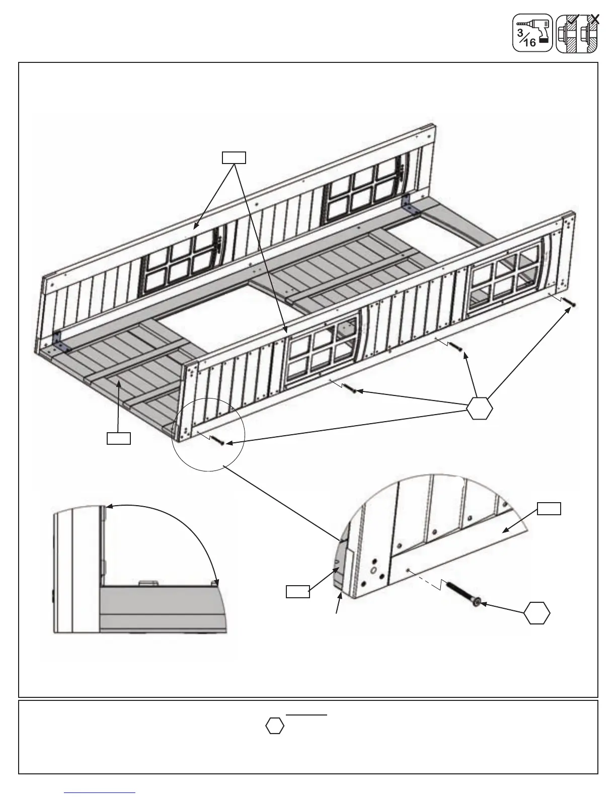
G:Pre-drillwitha3/16”drillbit,thenfastenthe(030)NarrowWindowPanelstothe(040)SWSidePanelwith4
(WL5)1/4x2-1/2”WaferLagsper(030)NarrowWindowPanel.(g.4.6and4.7)
Step 4: Swing Side Wall Panel Assembly
Part 3
030
040
WL5
Flush
90
o
ExampleofAngle
37 support@cedarsummitplay.com