Hardware
Fig. 24.8
030
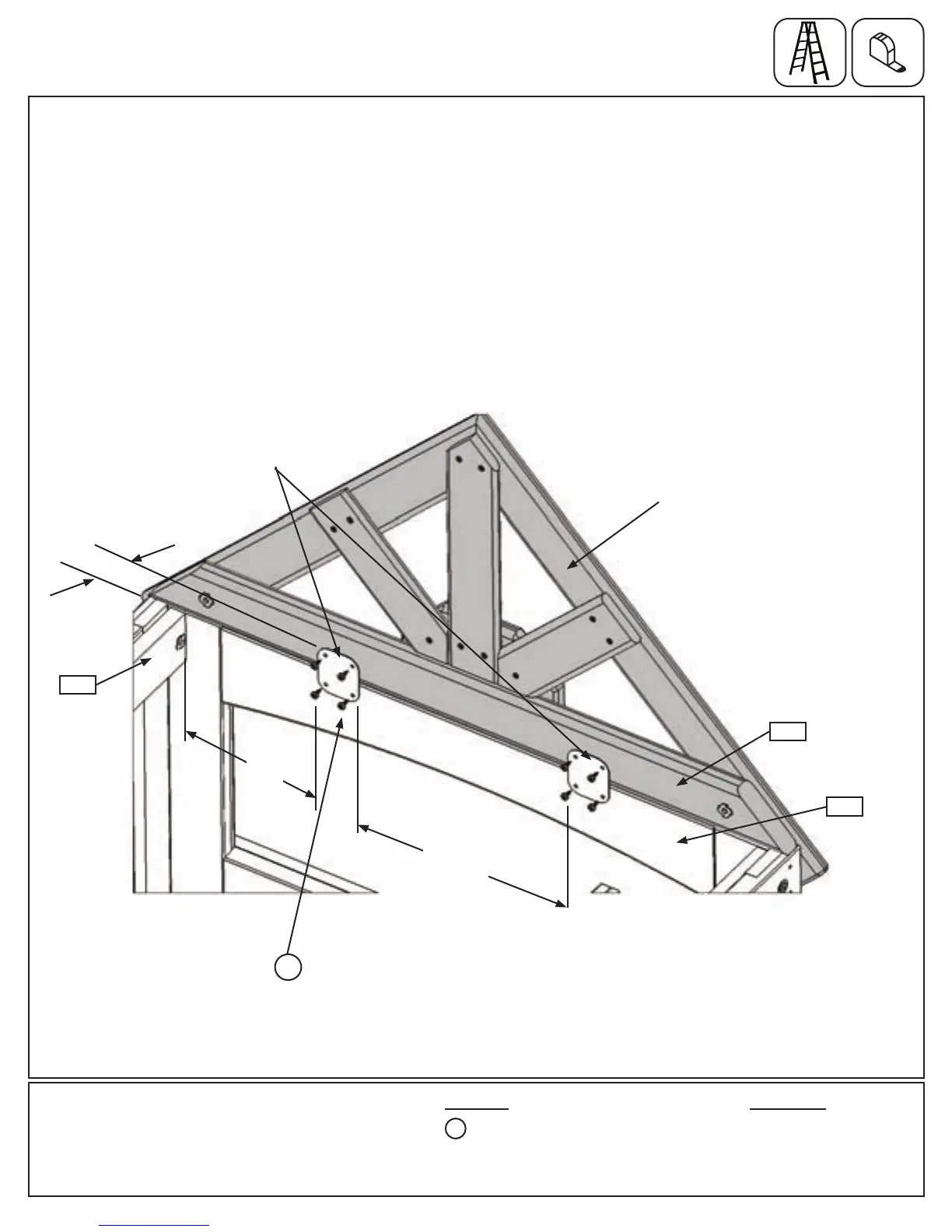
D:Frominsidetheassembly,measure9-3/4”fromtheinsideof(030)NarrowWindowPanelandplace1Flat
PanelBracketagainst(040)SWSidePaneland(222)GableBottom.ThetopoftheFlatPanelBracketshould
measure1-1/2”fromthebottomof(222)GableBottom.AttachFlatPanelBracketto(040)SWSidePaneland
(222)GableBottomwith4(S8)#12x3/4”PanScrewsasshowning.24.8.
E:Measure13”fromtherstFlatPanelBracketandplaceasecondFlatPanelBracketagainst(040)SWSide
Paneland(222)GableBottom.ThetopoftheFlatPanelBracketshouldmeasure1-1/2”fromthebottomof
(222)GableBottom.AttachFlatPanelBracketto(040)SWSidePaneland(222)GableBottomwith4(S8)#12
x3/4”PanScrewsasshowning.24.8.
Step 24: Attach Roof Support Assembly
Part 4
222
8 x #12 x 3/4” Pan Screw
FlatPanelBracket
040
S8
x4perbracket
9-3/4”
13”
RoofSupportAssembly
Inside Fort View
1-1/2”
S8
Other Parts
2 x Flat Panel Bracket
95 support@cedarsummitplay.com
 Loading...