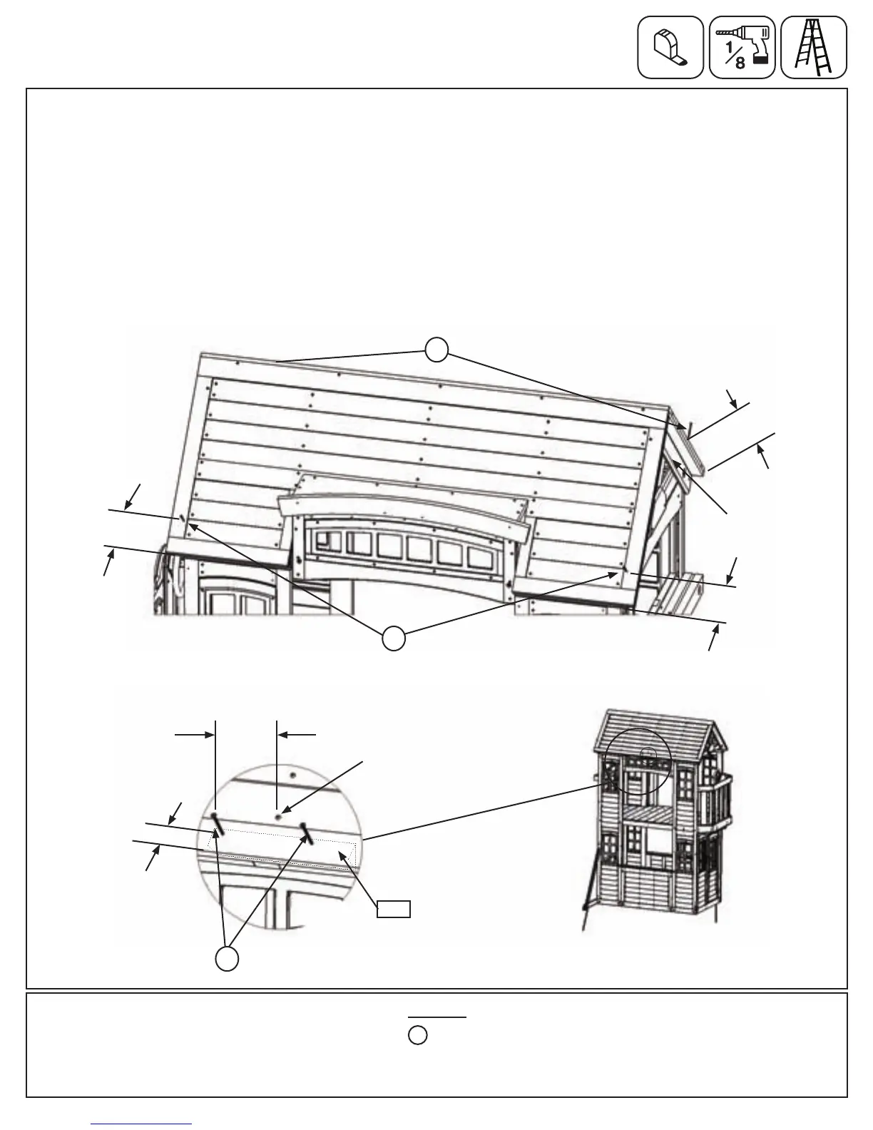
F:AteachcorneroftheRoofAssembly,measure5”upfromthebottomandpre-drillpilotholesintothecentreof
theRoofSupportAssemblieswitha1/8”drillbit.(g.25.7)
G:AttachtheRoofAssemblytotheRoofSupportAssemblieswith2(S3)#8x2-1/2”WoodScrewsperside,as
showning.25.7.
H:OntheBacksideofthefort,pre-drillpilotholesintotheRoofAssembly,3”oneithersideofthemiddleroof
screwand1-1/2”upfromthebottomoftheassemblyasshowning.25.8and25.9.Makesuretopre-drillinto
(150)RoofGussetwhichisbehindtheRoofAssembly.AttachRoofAssemblyto(150)RoofGussetwith2(S3)
#8x2-1/2”WoodScrews.(g.25.9)
Step 25: Attach Roof Assembly to Fort
Part 4
Fig. 25.7
150
6 x #8 x 2-1/2” Wood Screw
S3
Thisscrewison
centreofroof.
Hardware
Fig. 25.9
Fig. 25.8
Back
RoofSupport
Assembly
3”
1-1/2”
S3
(onescrewhiddenatback)
5”
5”
5”
Front
S3
S3
99 support@cedarsummitplay.com
 Loading...