7 8
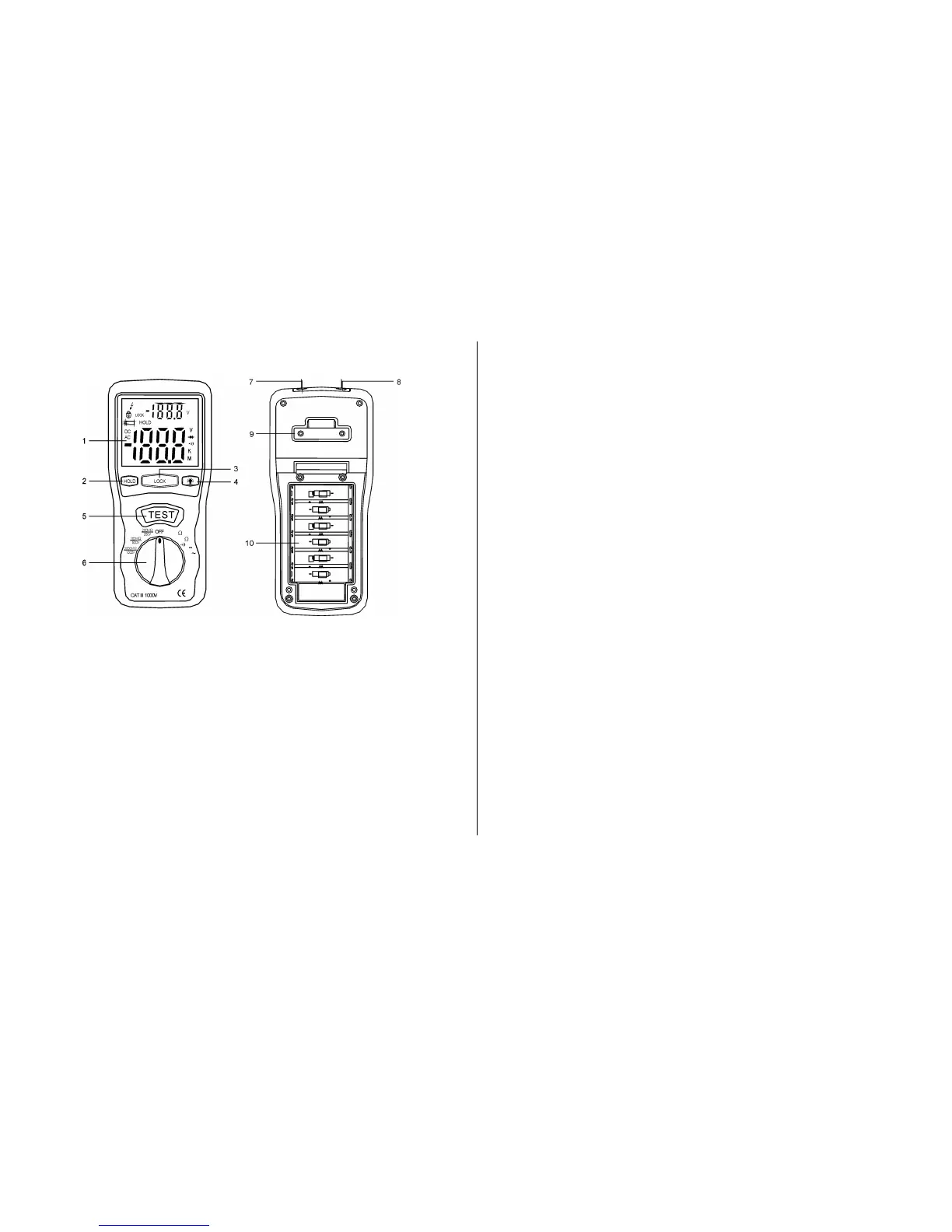
2. PARTS & CONTROLS
① Digital Display
② Data Hold Button
③ Lock Button
④ Backlight Button
⑤ Test Button
⑥ Rotary Function switch
⑦ VΩ Jack
⑧ COM input jack
⑨ Pothook
⑩ Battery Cover
3. BATTERY REPLACEMENT
3-1 How to connect test leads.
a). On MΩ Range: Connect the red test lead into the “VΩ”
terminal and the black lead into the “COM” terminal.
b) On 200Ω and ACV Range: Connect the red test lead into
the “VΩ” terminal and the black lead into terminal “COM”
3-2 Battery Check-UP & Replacement
a) As battery power is not sufficient. LCD will display .
Replacement of 6 pcs new batteries, type 1.5V size “AA”
is Required.
b). Place back the battery cover and four the screws.
3-3 Test leads check
Set the range select switch to the 200Ω range. With the tip
and alligator clip of the test leads connected. The indicator
should read 00.0Ω. When the leads are not connected the
display will read infinity indicated by “1”. This will ensure that
test lead are under working condition.
4. INSULATION RESISTANCE
MEASUREMENTS
a). Measurements at 200MΩ/250V This is the voltage used
for the majority of insulation resistance tests on normal
installation requirement. To measure insulation resistance,
press the test button to power on the tester. The LCD will
displayed the insulation resistance. Section VII indicated
 Loading...