Page 8 For technical questions, please call 1-888-866-5797. Item 40211
SAFETY OPERATION MAINTENANCEINSTALLATION
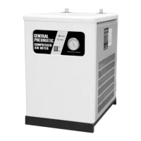
8. Route the three conductor electrical cord
(not included) through a UL approved
cable clamp (not included) and through the
Access Hole on the rear of the unit.
Rear
Access
Hole
Note: The three conductor electrical cord (not included)
must be rated for a minimum of 10-1/2 load rated amps,
and the plug must be three pronged (recommended
12 gauge, three conductor electrical cord).
Note: The schematic diagram below is provided for additional information and clarification.
Hot
Neutral
Ground
L
N
E
Green
Blue
Red
Brown
FAN
Red
Red
Green
Blue
Blue
Blue
Yellow
Error
Indicator
Power
Indicator
Refrigeration
Pressure Switch
Pressure
Switch
Power
Switch
Capacitor
Freezer
Overload
Protector
R
S
C
1 3
5
C
L
H
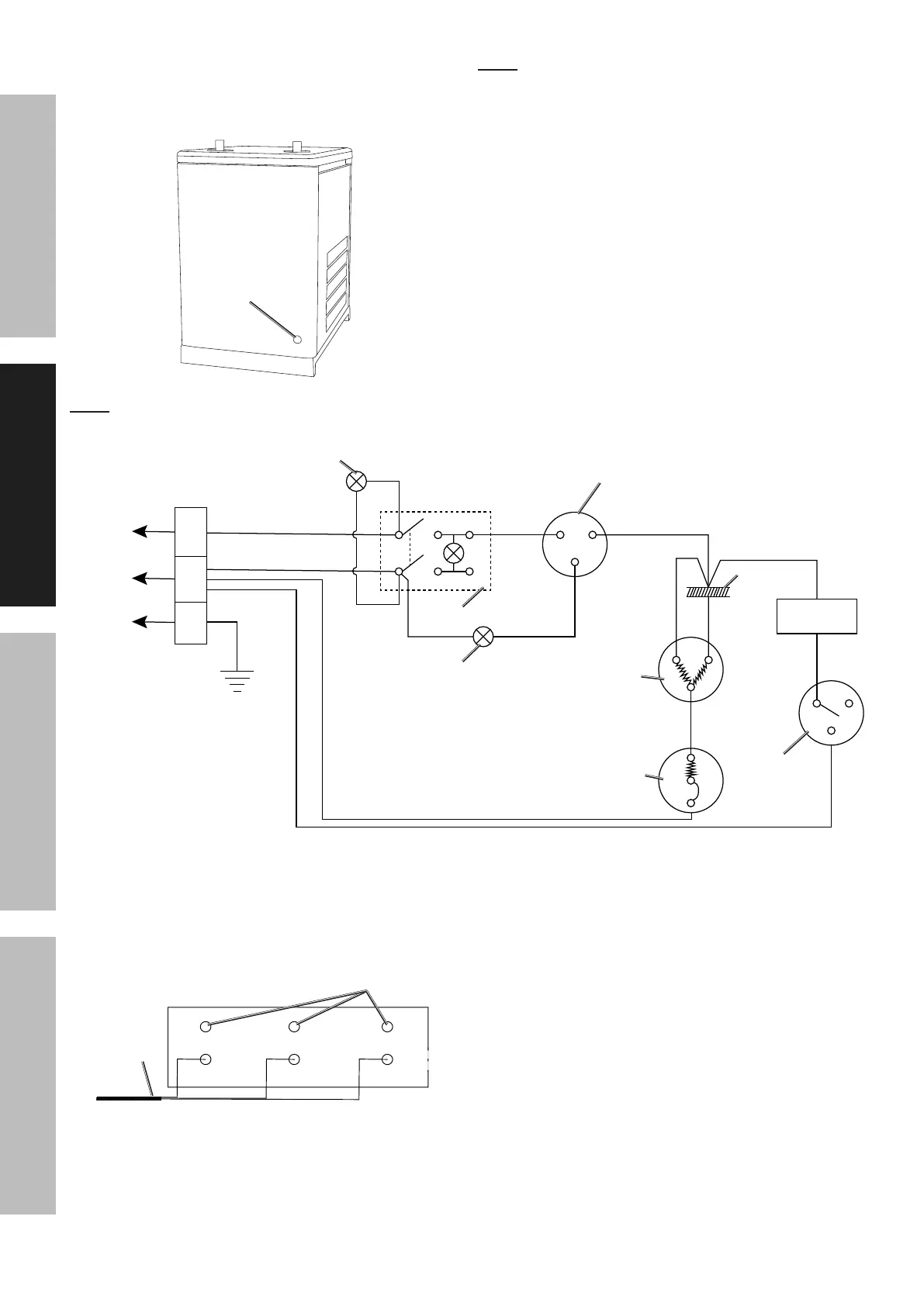
9. Locate the Terminal Strip inside the unit. Note
the top three wires on the Terminal Strip are
pre-wired from the factory. Connect the three
conductors of the electrical cord (not included)
to the Terminal Strip as illustrated below.
Green
(Hot)
Blue
(Neutral)
Green/Yellow
(Ground)
Black
(Hot)
White
(Neutral)
Green
(Ground)
Electrical
Cord
Pre-wired at
Factory
10. Make to route the electrical cord (not included)
in the interior of the unit to prevent interference
with the fan, hot components, etc.
11. Secure the UL approved cable clamp (not included)
to the Access Hole on the rear of the unit.
12. Secure the electrical cord (not included) within
the UL approved cable clamp (not included) to
prevent strain on the electrical connections.
13. Replace the Right Side Panel.
 Loading...