Page 8 ;&(%$*4.8"4,7%<'*#$"&8#=%/7*,#*%4,77%>?@@@?@AA?BCDC1 Item 60801
EF;6GH IJ6KFGLIM NFLMG6MFMO6E6GPJ
LMLGLFT%EIUF%STFEG6K%E6G%PJ0FEE6NSTH
%K*,9%$.*%6MGLK6%LNJIKGFMG%EF;6GH%LM;IKNFGLIM%#*4$"&8%,$%$.*%+*3"88"83%&2%$."#%
5,8',7%"847'9"83%,77%$*\$%'89*(%#'+.*,9"83#%$.*(*"8%+*2&(*%#*$%'/%&(%'#*%&2%$."#%/(&9'4$1
M&$*- For additional information regarding the parts listed in the following pages,
refer to the Assembly Diagram near the end of this manual.
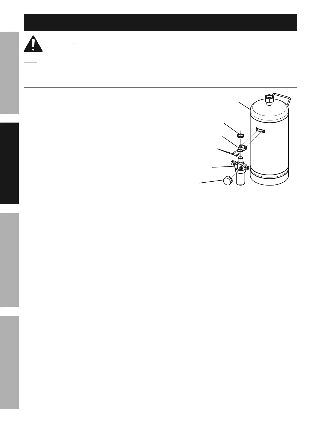
F##*5+7[
1. Attach Air Regulator (5) to the Tank (1) with
Attach Bracket (9) using the two Socket
Head Screws (8) and wrench tighten.
2. Remove the Compression Nut (22)
from the Air Regulator.
3. Insert the knob on the top of the
Air Regulator through the Bracket.
4. Align the tab on the Bracket with the recess
at gauge side of the Regulator, attach
Compression Nut and finger tighten until snug.
5. Attach Abrasive Outlet Pipe (11) and Abrasive
Hose (24) to Media Regulator (15).
6. Attach Air Hose (10) to Air Regulator
and Media Regulator.
S(,4Y*$%dDe
E&4Y*$%W*,9%
E4(*)#%d@e
J(*##'(*%
R,'3*%dAe
F"(%
K*3'7,$&(%dBe
O&5/(*##"&8%
M'$%d``e
G,8Y%d>e
;"3'(*%F-%%F"(%K*3'7,$&(%F##*5+7[