Page 5For technical questions, please call 1-800-444-3353.Impact Wrenches
Functional Description
Specications
Max. Air Pressure 90 PSI
Air Inlet
68425 3/8″ Impact Wrench
68424 1/2″ Impact Wrench
68423 3/4″ Impact Wrench
68429 1″ Impact Wrench
1/4″NPT
1/4″ NPT
3/8″ NPT
1/2″ NPT
Maximum Torque
68425 3/8″ Impact Wrench
68424 1/2″ Impact Wrench
68423 3/4″ Impact Wrench
68429 1″ Impact Wrench
300 ft.-lb / 11,000 RPM
700 ft.-lb / 8000 RPM
1400 ft-lb / 5500 RPM
2000 ft-lb / 5000 RPM
Average Air Consumption
68425 3/8″ Impact Wrench
68424 1/2″ Impact Wrench
68423 3/4″ Impact Wrench
68429 1″ Impact Wrench
5 CFM @ 90 PSI
6 CFM @ 90 PSI
9 CFM @ 90 PSI
10 CFM @ 90 PSI
* Maximum torque at stated maximum air pressure. Excess air
pressure is hazardous and may cause tool failure or injury.
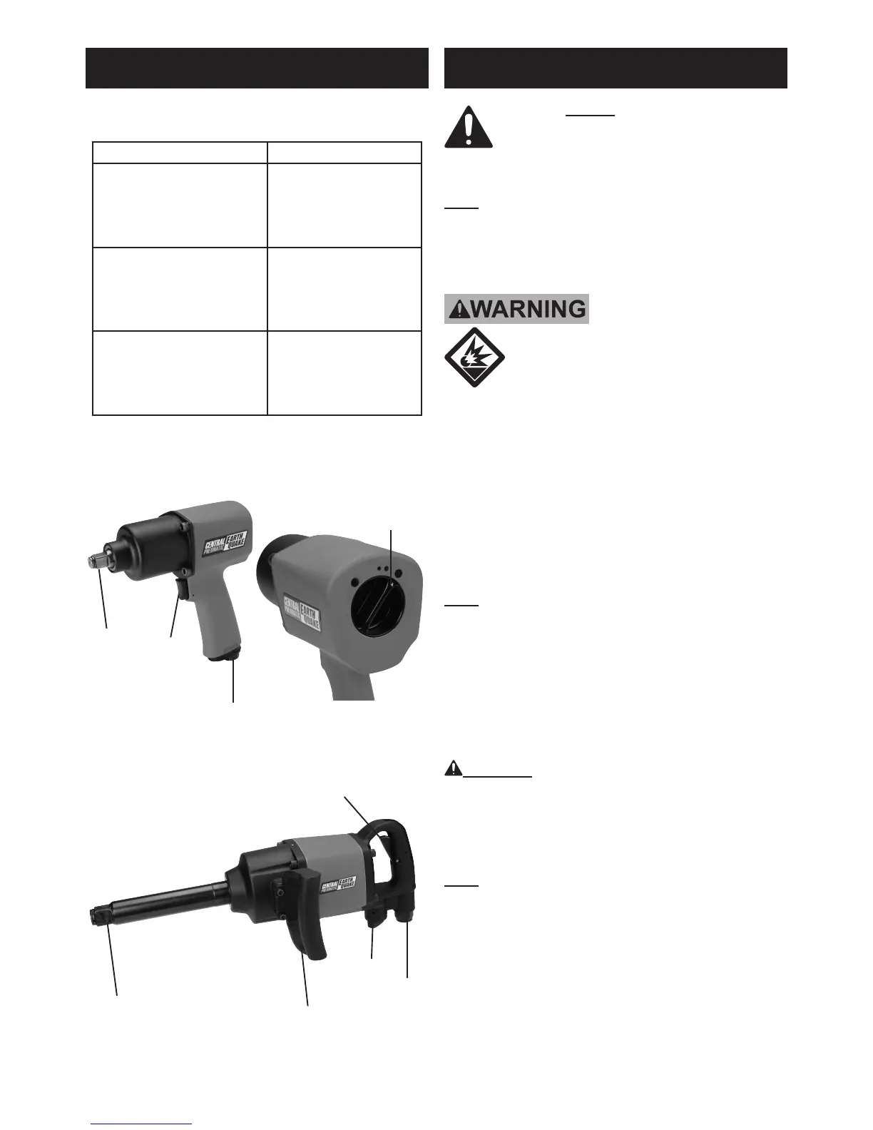
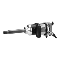
Components and Controls
Initial Tool Set Up/Assembly
Read the ENTIRE IMPORTANT
SAFETY INFORMATION section at the
beginning of this manual including
all text under subheadings therein
before set up or use of this product.
Note: For additional information regarding the
parts listed in the following pages, refer to the
Assembly Diagram near the end of this manual.
Air Supply
TO PREVENT SERIOUS INJURY
FROM EXPLOSION:
Verify compressoris off before setup. Use
only clean, dry, regulated, compressed air
to power this tool. Do not use oxygen, carbon
dioxide, combustible gases, or any other bottled gas
as a power source for this tool.
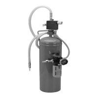
1. Incorporate a lter, regulator with pressure gauge,
oiler, in-line shutoff valve, and quick coupler for
best service, as shown on Figure A on page 6
and Figure B on page 7. An in-line shutoff
ball valve is an important safety device because
it controls the air supply even if the air hose
is ruptured. The shutoff valve should be a
ball valve because it can be closed quickly.
Note: If an automatic oiler system is not
used, add a few drops of Pneumatic Tool Oil to
the air inlet before operation. Add a few more
drops after each hour of continual use.
2. Attach an air hose to the compressor’s air outlet.
Connect the air hose to the air inlet of the tool.
Other components, such as a quick connect
plug and quick connect coupler, will make
operation more efcient, but are not required.
WARNING! TO PREVENT SERIOUS INJURY
FROM ACCIDENTAL OPERATION:
Do not install a quick coupler on the tool.
Such a coupler contains an air valve that will
allow the air tool to retain pressure and operate
accidentally after the air supply is disconnected.
Note: Air ow, and therefore tool performance, can
be hindered by undersized air supply components.
3. The air hose must be long enough to reach
the work area with enough extra length to
allow free movement while working.
4. Turn on the air compressor according to
the manufacturer’s directions and allow it
to build up pressure until it cycles off.
Regulator
Knob
Anvil
Air Inlet
Trigger
Models 68423, 68424 and 68425
Model 68429
Anvil
Trigger
Side Handle
Air
Inlet
Regulator
Knob