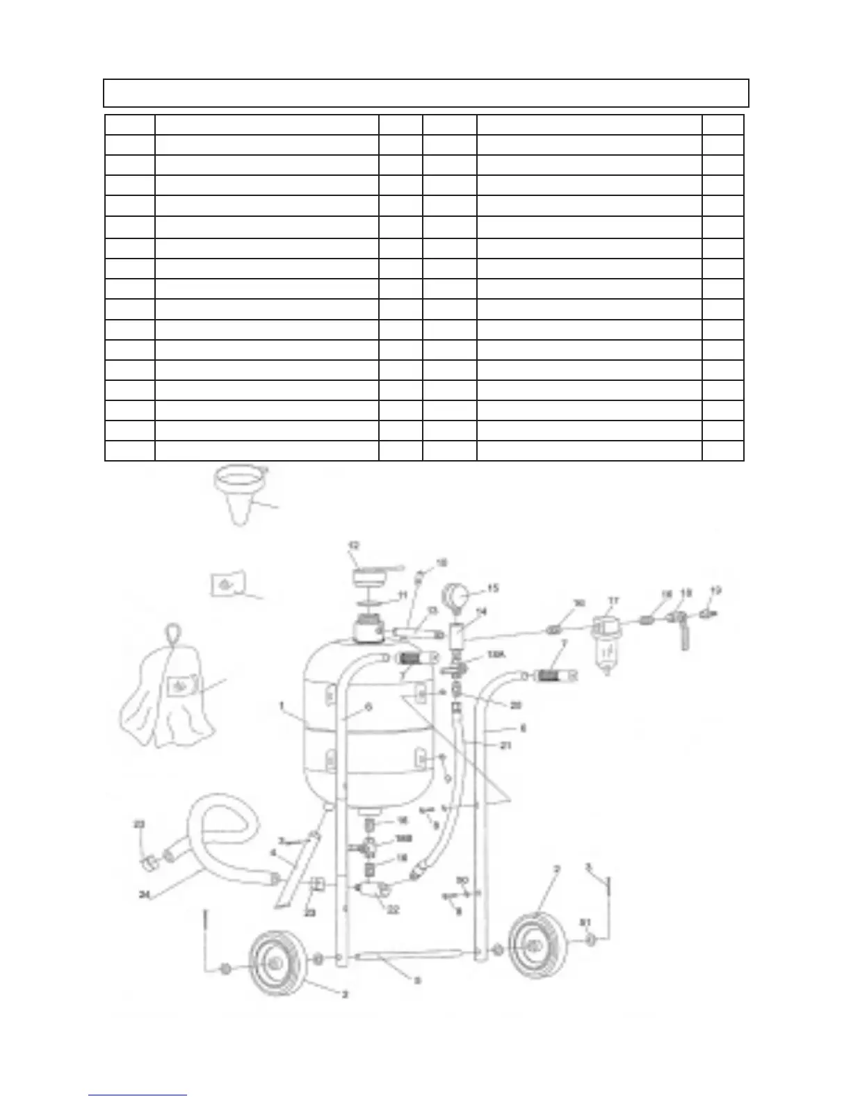
PARTS LIST & ASSEMBLY DIAGRAM - AIR BLASTER
SKU 95014 For technical questions, please call 1-800-444-3353 PAGE 15
30
30A
29
Part # Description QTY Part # Description QTY
1 Tank 1 17 Water Trap 1
2 Wheel 2 18 Air Supply Valve (3/8”) 1
3 Cotter Pin 3 18A Throttling Valve (3/8”) 1
4 Front Foot 1 18B Abrasive Control Valve (3/8”) 1
5 Wheel Axle 1 19 Inlet Connector 1
6 Handle Bar 2 20 Male Connector 1
7 Handle Grip 2 21 Air Hose 1
8 Pan Screw 4 22 Abrasive Outlet Manifold 1
9 Hex Nut 4 23 Hose Clamp 2
10 Safety Valve 1 24 Abrasive Hose 1
11 O-Ring 1 29 Funnel 1
12 Tank Filler Cap 1 30 Hood 1
13 Joint Pipe 1 30A Hood Lens 1
14 Intake Manifold 1 50 Washer 4
15 Pressure Gauge 1 51 Wheel Washer 4
16 Maile Connector (3/8”) 5
NOTE:
Some parts are listed and shown
for illustration purposes only,
and are not available individually
as replacement parts.