Installation
The Central ROC Residential Optima
Concealed Pendent Sprinklers must be
installed in accordance with the following
instructions:
NOTES
Damage to the fusible Link Assembly
during installation can be avoided by
handling the sprinkler by the frame arms
only (i.e., do not apply pressure to the
fusible Link Assembly), and by using the
appropriate sprinkler wrench. Damaged
sprinklers must be replaced.
A leak tight 1/2 inch NPT sprinkler joint
should be obtained with a torque of 7 to
14 ft.lbs. (9,5 to 19,0 Nm). A maximum of
21 ft.lbs. (28,5 Nm) of torque is to be
used to install 1/2 inch NPT sprinklers.
Higher levels of torque may distort the
sprinkler inlet with consequent leakage
or impairment of the sprinkler.
Step 1. The sprinkler must only be
installed in the pendent position and with
the centerline of the sprinkler perpen-
dicular to the mounting surface.
Step 2. Remove the Protective Cap.
Step 3. With pipe thread sealant applied
to the pipe threads, and using the ROC
Wrench shown in Figure 1, install and
tighten the Sprinkler/Support Cup
Assembly into the fitting. ROC Wrench
will except a 1/2 inch ratchet drive.
Step 4. Replace the Protective Cap by
pushing it upwards until it bottoms out
against the Support Cup. The Protective
Cap helps prevent damage
to the Deflector and Arms during ceiling
installation and/or during application of
the finish coating of the ceiling. It may
also be used to locate the center of the
clearance hole by gently pushing the
ceiling material up against the center
point of the Cap.
NOTE
As long as the Protective Cap remains in
place, the system is considered to be
"Out of Service"
Step 5. After the ceiling has been
completed with the 2-1/2 inch (66,7 mm)
diameter clearance hole and in prepara-
tion for installing the Cover Plate
Assembly, remove and dis-
card the Protective Cap, and verify that
the Deflector moves up and down freely.
If the Sprinkler has been damaged and
the Deflector does not move up and
down freely, replace the entire Sprinkler
assembly. Do not attempt to modify or
repair a damaged sprinkler.
Step 6. Screw on the Cover Plate/
Retainer Assembly until its flange just
comes in contact with the ceiling. Do not
continue to screw on the Cover Plate/
Retainer Assembly such that it lifts a
ceiling panel out of its normal position. If
the Cover Plate/Retainer Assembly
cannot be engaged with the Support Cup
or the Cover Plate/Retainer Assembly
cannot be engaged sufficiently to contact
the ceiling, the Sprinkler Fitting must be
repositioned.the Sprinkler Fitting must be
repositioned.
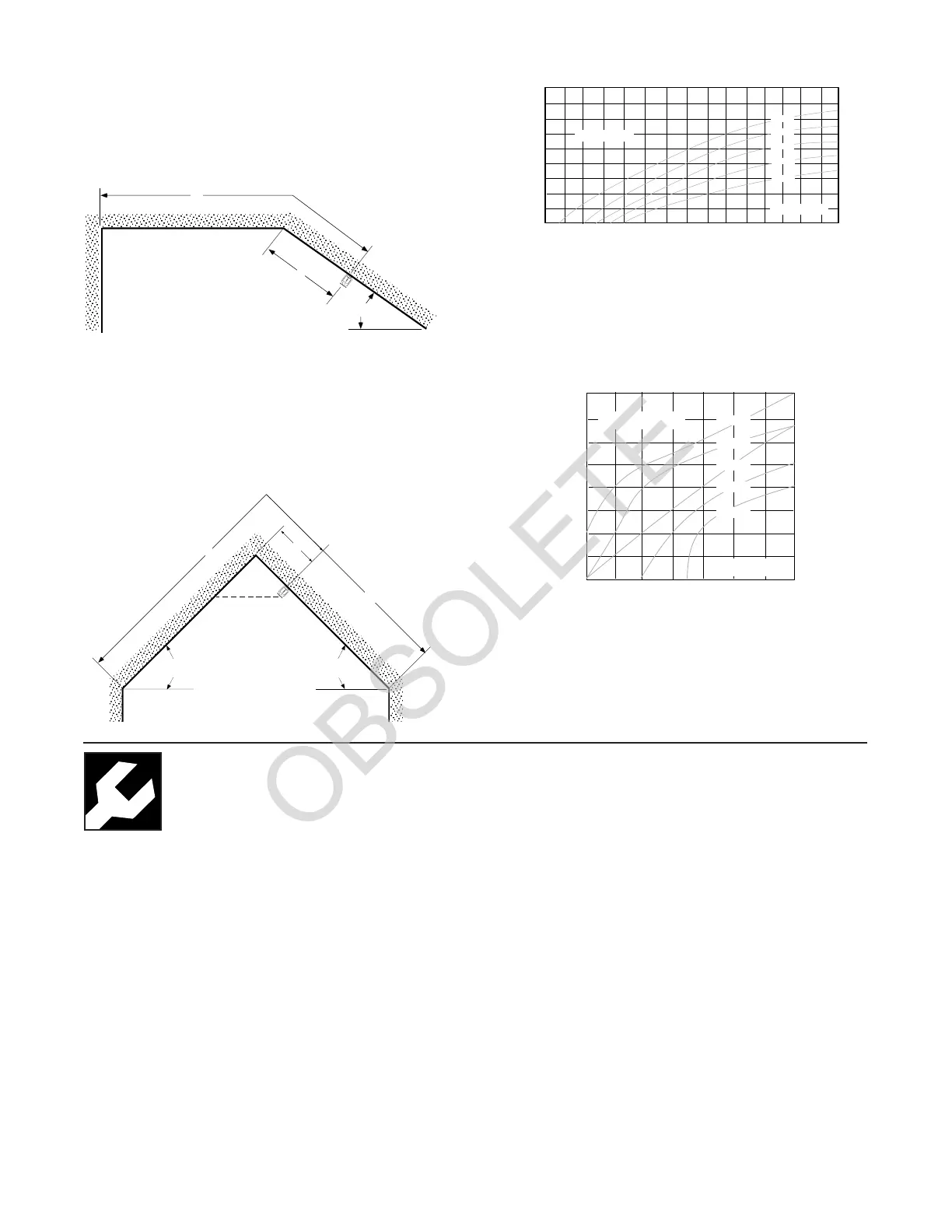
A — NFPA minimum of 4", maximum 1/2 of the Listed
spacing that the sprinkler was calculated for.
D — Distance to opposing sloped ceiling.
F & G — Acceptable for angles 0° to 60°.
Figure 13 - Obstruction to Discharge by Intersecting Flat Ceiling
If “D” is “Obstructed” per Figure 13 Graph, then “D” is to be
considered the area of coverage and additional sprinklers
along the horizontal ceiling will be necessary. Only if “D” is
“Acceptable” can “A” be considered 1/2 of the maximum
Listed spacing that the sprinkler was calculated for. Dimen-
sion “A” is measured along the slope.
A — Maximum 1/2 of the Listed spacing that the sprinkler
was calculated for.
D — Distance to intersecting horizontal ceiling.
F — Acceptable for angles 0° to 60°.
Figure 14 - Obstruction to Discharge by an Opposing Sloped Ceiling
If “D” is “Obstructed” per Figure 14 Graph, then the
horizontal distance to the opposing slope is the extent of
coverage and additional sprinklers will be necessary to
protect the remainder of the opposing slope. Only if “D” is
“Acceptable” can “A” equal 1/2 of the maximum Listed
spacing that the sprinkler was calculated for. Dimension “A”
is measured along the slope.
D
F
A
0° 4° 8° 12° 16° 20° 24° 28° 32° 36° 40° 44° 48° 52° 56° 60°
10'
9'
8'
6'
5'
4'
3'
2'
1'
7'
"D"
(in feet)
"F"
(in degrees)
Obstructed
Acceptable
20' x 20'
18' x 18'
16' x 16'
14' x 14'
12' x 12'
A
D
A
GF
5'
4'
3'
2'
1'
"D"
(in feet)
"F" or "G"
(whichever is greater)
(in degrees)
Obstructed
10° 15° 20° 25° 30° 35° 40° 45°
Acceptable
20' x 20'
18' x 18'
16' x 16'
14' x 14'
12' x 12'
 Loading...