EAGLEHAWK NX CONTROLLER – PRODUCT DATA
EN0Z-1039GE51 R0319
5
M-Bus Repeaters
The M-Bus can be extended to 1,000 meters, depending on
the communication rate, and provided that the electrical limi-
tations are observed. For details refer to the EAGLEHAWK
NX Controller – Installation & Commissioning Instructions
(EN1Z-1039GE51).
For bus length extension, M-Bus repeaters can be used, but
have not been tested by Honeywell. Hence, it is the
responsibility of the installing / commissioning personnel to
ensure proper functioning.
M-Bus Master Specifications
For a detailed description of the M-Bus functionality, please
refer to the M-Bus Online Help.
Physical Layer
RS232 to PW3/PW20/PW60
Physical connector: RS232 / RJ45 socket (see Fig. 5)
Cable order number: XW586
Communication rates: 300, 2,400, and 9,600 bps are
supported, individually per M-Bus
slave.
Max. no. of devices: 60 (excluding the EAGLEHAWK NX
controller)
Cable and wiring specifications: See EAGLEHAWK NX –
Installation & Commissioning Instructions (EN1Z-1039GE51).
Address Range
M-Bus slaves can have a primary address between 1 and
250.
Measurement Cycle
Individually per M-Bus slave, the measurement cycle can be
configured from 1 to 604,800 sec (i.e., 1 second to 7 days).
Modbus Connection
The EAGLEHAWK NX controller can function as a Modbus
Master/Slave.
For Modbus RTU, the RS485 wiring rules must be followed.
Wiring Topology
Only daisy-chain wiring topology is allowed.
MODBUS
MASTER
MODBUS
SLAVE
MODBUS
SLAVE
MODBUS
SLAVE
MODBUS
SLAVE
Fig. 7. Allowed Modbus wiring topology
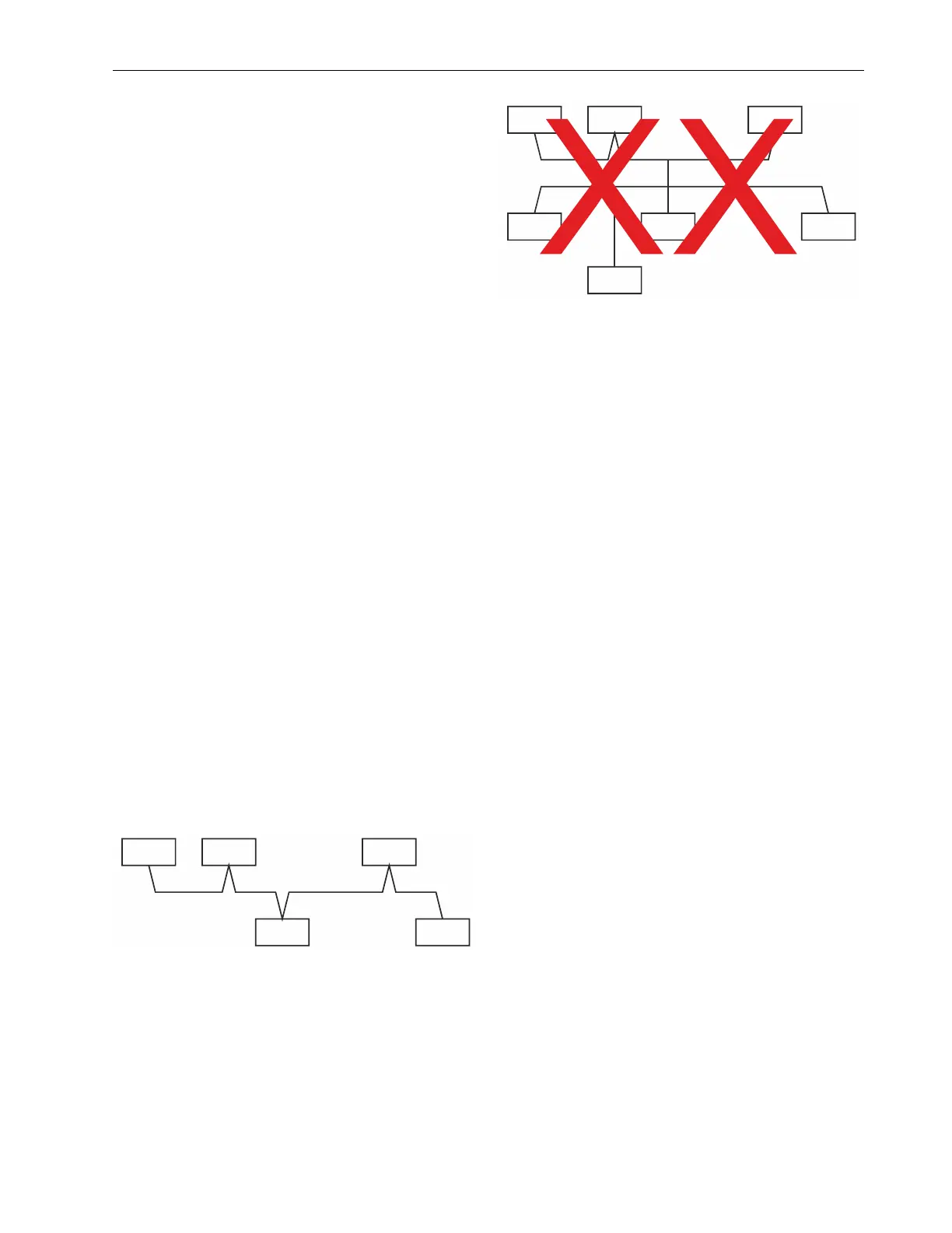
Other wiring topologies (e.g., star wiring, or mixed star wiring
and daisy chain wiring) are prohibited; this is to avoid com-
munication problems of the physical layer.
MODBUS
MASTER
MODBUS
SLAVE
MODBUS
SLAVE
MODBUS
SLAVE
MODBUS
SLAVE
MODBUS
SLAVE
MODBUS
SLAVE
Fig. 8. Prohibited Modbus wiring topology (example)
Cables
See section "EIA 485 Cable Specifications" in EAGLEHAWK
NX Controller – Installation & Commissioning Instructions
(EN1Z-1039GE51).
Use shielded, twisted pair cable J-Y-(St)-Y 2 x 2 x 0,8.
You must use three wires:
One wire for D1 = Modbus +
One wire for D0 = Modbus –
One wire for the signal common
When using one pair for D1 and D0 and one wire of another
pair for the signal common, CAT5 cable may also be used.
For connection details, see EAGLEHAWK NX Controller –
Installation & Commissioning Instructions (EN1Z-1039GE51).
Shielding
Shielding is especially recommended when the Modbus cable
is installed in areas with expected or actual electromagnetic
noise. Avoiding such areas is to be preferred.
Use shielded, twisted pair cable J-Y-(St)-Y 2 x 2 x 0,8 and
connect the shield to a noise-free earth ground – only once
per Modbus connection.
RS485 Repeaters
RS485 repeaters are possible, but have not been tested by
Honeywell. Hence, it is the responsibility of the installing /
commissioning personnel to ensure proper functioning.
NOTE: Each Modbus segment requires its own line
polarization and line termination.
Modbus Specifications
For Modbus RTU and TCP specifications, please refer to the
COACH AX document entitled Niagara AX-3.x Modbus
Guide.