Do you have a question about the CEP 8706GU and is the answer not in the manual?
Details installation and operation instructions for temporary power branch distribution systems.
Specifies ratings and protection for 50 amp units and 20 amp outlets.
Explains GFCI protection against electrocution hazards from ground faults.
General warning about handling electricity and safety devices with care.
Unit requires grounded supply and proper over-current protection.
Step-by-step procedure to test GFCI modules on all models.
Explains conditions causing GFCI modules to trip and how to reset them.
Explains circuit breaker tripping is due to overloads or short circuits.
Describes the NEMA Type 3R enclosure for outdoor use and protection.
This document outlines the installation, operation, and maintenance of the CEP 6506GU/G and 8706GU/G temporary branch power distribution units, which are equipped with Ground Fault Circuit Interrupter (GFCI) protection for personnel safety. These units are designed to provide temporary power distribution in various settings, prioritizing user safety through advanced ground fault protection.
The CEP temporary power distribution units serve as portable branch distribution systems, delivering power to multiple outlets while safeguarding users from electrical shock hazards caused by ground faults. Ground faults occur when current leaks from an electrical circuit, potentially leading to dangerous electric shocks. These units are specifically engineered to detect and interrupt such fault currents rapidly, significantly reducing the risk of electrocution.
The core safety feature of these units is the integration of UL-listed Class A, Group I GFCI interrupters. These interrupters are highly sensitive, capable of detecting fault currents as low as 3-6 milliamperes. Upon detection, they can shut off the power within 1/40th of a second, a speed crucial for preventing severe injury or fatality. While GFCI modules do not eliminate the possibility of a shock, they critically limit its duration to a period considered safe for normally healthy individuals. It is important to note that GFCI modules specifically protect against line-to-ground faults and do not offer protection against overloads or short circuits. Overload and short circuit conditions are handled by individual circuit breakers within the unit. The units are designed to operate on a grounded electrical supply system and will not function if the power source is ungrounded. Proper over-current protection, as per the National Electric Code, Article 240, must be used on the supply circuit feeding these distribution units.
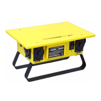
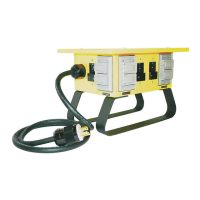
The units are designed for ease of use and safety in temporary power applications. They are equipped with multiple 20-amp, 120-volt outlets, each individually protected by circuit breakers and GFCI circuit modules. The 20-amp receptacles come in both U-Ground and Twist-Lock configurations, offering versatility for different equipment connections.
Before initial use or after any maintenance, a crucial "Test Procedure" must be followed to ensure the GFCI modules are functioning correctly. This involves connecting the unit to an appropriate power source, ensuring all circuit breakers are in the "on" position, and then pressing the test button on each individual GFCI module. A successful test will result in the unit tripping, indicating the GFCI is active. Subsequently, pressing the reset button should cause the indicator light to illuminate, confirming the unit is ready for use. This test procedure should be repeated for all GFCI modules within the unit.
The units are housed in NEMA Type 3R enclosures, making them suitable for outdoor use. These enclosures protect the internal components from windblown dust, water, and external ice or sleet, ensuring reliable operation in various environmental conditions.
Troubleshooting guidance is provided for common issues. If a GFCI module trips, it could indicate several abnormal conditions in the supply-side circuit, such as a transposed hot and neutral conductor, an open (disconnected) hot conductor, or an excessive voltage imbalance between line 1 and line 2 circuits, possibly due to an open neutral conductor in the supply. Once these supply-side issues are corrected, the unit can be reset by completely removing and reapplying line power, followed by repeating the GFCI test procedure.
When a GFCI module trips, users are advised to attempt a reset by pressing the reset switch, while being cautious of potential hazards. If the module resets, it suggests a momentary fault that has cleared. If it trips immediately again, the fault is persistent, and the GFCI is performing its safety function. To locate the fault, all loads should be disconnected, and a reset attempted. If the module resets, loads should be reconnected one at a time until the faulted load is identified. Tools, appliances, and extension cords in the faulted circuit should then be inspected and repaired or replaced if necessary.
Circuit breaker tripping, distinct from GFCI tripping, indicates an overload or short circuit in its individual load circuit. To reset a tripped circuit breaker, the handle must first be switched to the "OFF" position and then to the "ON" position, after the fault in the load circuit has been corrected or removed.
The manual also addresses "Nuisance Tripping," which can occur due to capacitive leakage in cables. For 120-volt systems, there's a limit to the length of cable that can be run before sufficient leakage to ground causes a GFCI to trip. Individual 120-volt branch circuit load cords should generally be limited to 100 feet in length to prevent this.
Two indicator lights provide additional operational feedback:
Regular maintenance and repair are crucial for ensuring the continued safe operation of these power distribution units. All electrical power supply to the unit MUST be turned OFF and DISCONNECTED before any repair or maintenance work begins. This work must only be performed by a trained and competent electrician to prevent serious injury or death.
A critical warning is issued regarding the physical condition of the unit: if any parts or components appear to be missing, broken, or show signs of damage, the unit's use must be DISCONTINUED IMMEDIATELY. Users are explicitly prohibited from modifying these devices in any way. Instead, worn or damaged components must be replaced. Failure to adhere to these guidelines could result in serious personal injury or death.
The manual includes a detailed parts breakdown, complete with an exploded diagram and a table listing each component by ID, part number, and description. This breakdown facilitates the identification and ordering of replacement parts, ensuring that only appropriate and compatible components are used for repairs. Examples of listed parts include the G Box Lid, Box Legs, Rugged Frame, various TL (Twist-Lock) and UG (U-Ground) receptacles, receptacle covers and gaskets, interior circuit breaker panels, snap-in GFCI breakers, GFCI modules, ground bars, neutral bars, and end caps for neutral bars. Components marked with an asterisk (*) are not shown on the drawing but are included in the parts list for comprehensive maintenance. This detailed parts list empowers qualified technicians to perform necessary repairs and replacements, thereby extending the lifespan of the unit and maintaining its safety features.
| Outlets | 8 |
|---|---|
| Plug Type | NEMA 5-15P |
| Outlet Type | NEMA 5-15R |
| Input Frequency | 60 Hz |
| Weight | 0.45 kg |