26
model no. 060-1310-2 I contact us: 1-844-428-7277
IMPORTANT: Install new paddles so wear
indicator holes are positioned on the
right side of unit.
2. Secure each paddle to side plates with four
hex bolts, four flat steel washers and four
flange nuts.
3. Secure each paddle to centre plate with two
hex bolts and two flange nuts.
4. Torque paddle hardware to 5.6 N m – 10.2 N m
50 lb per inch to 90 lb per inch.
DO NOT overtighten.
5. Rotate auger paddles by hand to ensure
paddles are secure and do not interfere with
housing.
6. Return unit to upright position.
7. Remove slack from auger cable. See
Adjusting Control Cable on page 14.
8. Reconnect spark plug wire and turn fuel
valve to the on position.
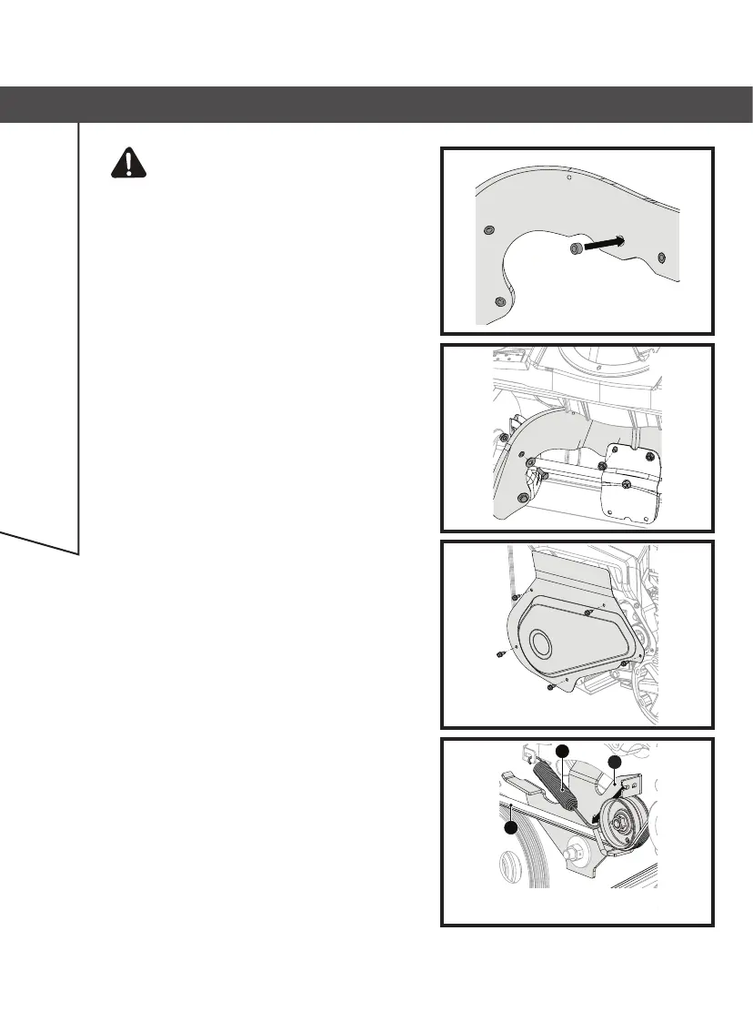
REPLACE DRIVE BELT
Removing Drive Belt
1. Stop engine and wait for all moving parts to stop
and for hot parts to cool.
2. Disconnect spark plug wire.
3. Remove belt cover hardware and remove cover.
Retain all parts (Fig. 27).
See Fig. 28.
4. Disconnect extension spring from idler arm.
5. Remove belt from drive sheave, idler sheave and
engine sheave.
1.Extension Spring
2.Idler Arm
3.Drive Belt
1
3
2
Fig. 26
Fig. 28
Fig. 27
Fig. 25
STORING AND MAINTENANCE