SECTION
7
AIRPLANE
&
SYSTEMS
DESCRIPTIONS
eo.";m,
402
C
MODEL
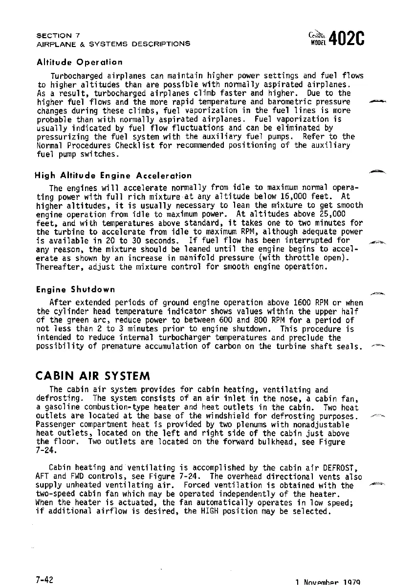
Altitude
Operation
Turbocharged airplanes
can
maintain higher
power
settings
and
fuel
flows
to higher
altitudes
than are possible with normally aspirated airplanes.
As
a
result,
turbocharged airplanes climb
faster
and
higher.
Due
to the
higher fuel flows
and
the
more
rapid temperature
and
barometric pressure
changes
during these climbs, fuel vaporization in the fuel
lines
is
more
probable than with normally aspirated airplanes.
Fuel
vaporization
is
usually indicated
by
fuel
flow
fluctuations
and
can
be
eliminated
by
pressurizing the fuel system with the auxiliary fuel
pumps.
Refer to the
Normal
Procedures Checklist for
recommended
positioning of the auxiliary
fuel
pump
switches.
High
Altitude
Engine
Acceleration
The
engines will accelerate normally
from
idle
to
maximum
normal
opera-
ting
power
with
full
rich mixture
at
any
altitude
below
16,000
feet.
At
higher
altitudes,
it
is
usually necessary to lean the mixture to get
smooth
engine operation
from
idle
to
maximum
power.
At
altitudes
above
25,000
feet,
and
with temperatures
above
standard,
it
takes
one
to
two
minutes for
the turbine to accelerate
from
idle
to
maximum
RPM,
although adequate
power
is
available in
20
to
30
seconds.
If
fuel
flow
has
been
interrupted
for
any
reason, the mixture should
be
leaned
until
the engine begins to accel-
erate
as
shown
by
an
increase in manifold pressure (with
throttle
open).
Thereafter, adjust the mixture control for
smooth
engine operation.
Engine
Shutdown
After extended periods of
ground
engine operation
above
1600
RPM
or
when
the cylinder
head
temperature indicator
shows
values within the upper half
of the green
arc,
reduce
power
to
between
600
and
800
RPM
for
a period of
not
less
than 2 to 3 minutes
prior
to engine
shutdown.
This procedure
is
intended to reduce internal turbocharger temperatures
and
preclude the
possibility
of premature accumulation of carbon
on
the turbine
shaft
seals.
CABIN
AIR
SYSTEM
The
cabin
air
system provides for cabin heating, ventilating
and
defrosting.
The
system consists of
an
air
inlet
in the nose, a cabin fan,
a gasoline combustion-type heater
and
heat
outlets
in the cabin.
Two
heat
outlets
are located
at
the base of the windshield
for
defrosting purposes.
~~
Passenger
compartment
heat
is
provided
by
two
plenums
with nonadjustable
heat
outlets,
located
on
the
left
and
right
side of the cabin
just
above
the
floor.
Two
outlets
are located
on
the forward bulkhead, see Figure
7-24.
Cabin
heating
and
'ventilating
is
accomplished
by
the cabin
air
DEFROST,
AFT
and
FWD
controls, see Figure 7-24.
The
overhead directional vents also
supply unheated ventilating
air.
Forced
ventilation
is
obtained with the
~
two-speed cabin fan
which
may
be
operated independently of the heater.
When
the heater
is
actuated, the fan automatically operates in
low
speed;
if
additional airflow
is
desired, the
HIGH
position
may
be
selected.
7-42
1 NnvPmhiOr 1
Q7Q
 Loading...