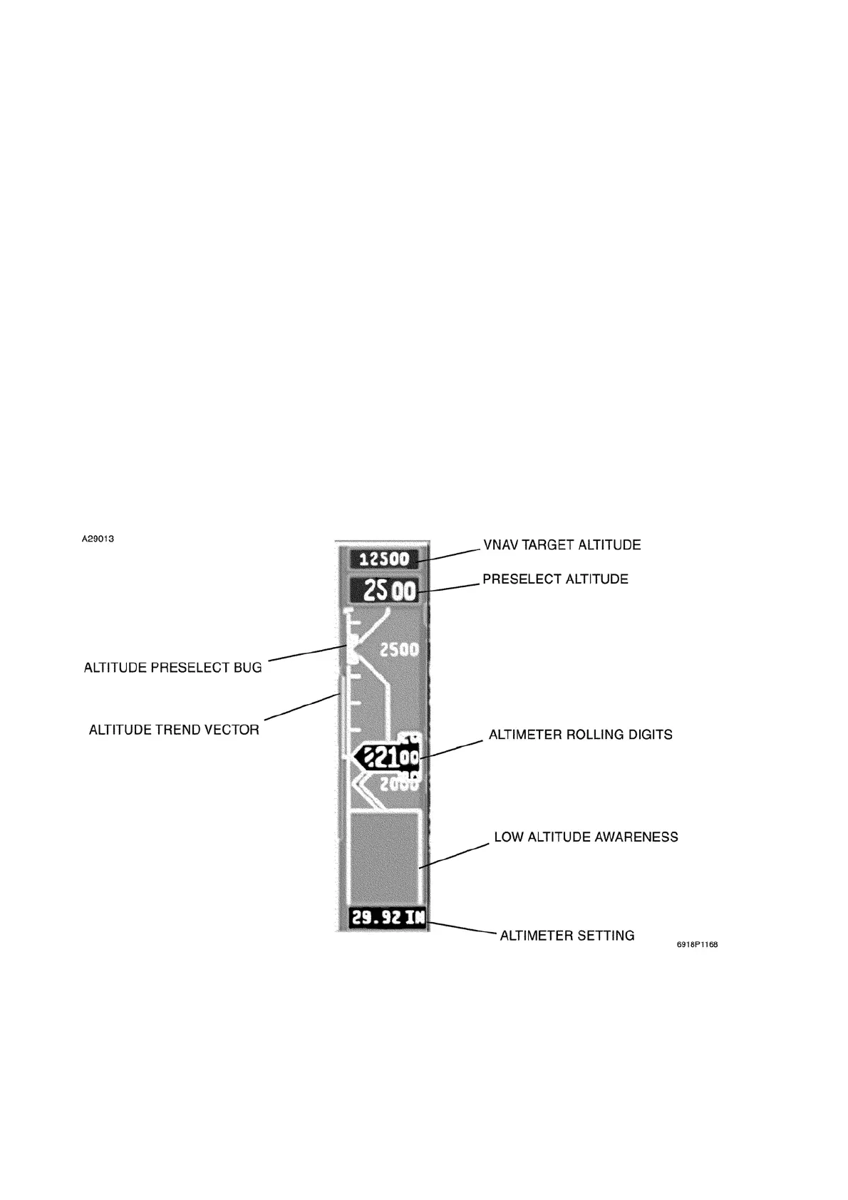
The scale is labeled in 500 foot intervals, and single line chevrons are located at each 500 foot
increment. Double line chevrons are located at each 1000 foot increment. The chevrons extend back
to the approximate midpoint of the altitude tape and are connected with each other by a vertical line.
The left side of the “rolling digit” window will has the same angle as the chevrons.
The barometric pressure setting is controlled by a BARO knob in the middle of the DC-550 controller.
The BARO knob also functions as the STD button and allows a change to a baro setting of 29.92 in.
Hg. (or 1013 millibars) by pressing it, "STD" will show when button is pressed. The baro correction
setting display is located just below the altitude tape. The BARO knob will change the altitude
correction by 0.01 in. Hg. per click.
An altitude trend vector is displayed on the left edge of the altitude tape and provides an indication of
the rate of altitude change. The trend vector extends vertically from the apex of the current altitude
display window. The vector extends up for positive vertical trends and down for negative values. The
vector represents a prediction of what the altitude will be in six seconds if the current vertical speed is
maintained.
Standby altitude indications are available from the standby flight display (standby airspeed/ altitude/
attitude indicator) which is discussed under Standby Flight Display below in this section.
TYPICAL ALTITUDE DISPLAY
Figure 3-3
Cessna Citation XLS - Instrumentation & Avionics
 Loading...