Registration
Number,
1-6
Surfaces,
4
Regulator, voltage,
2-4
aluminum,
4-2
Reverse
Polarity Contactor,
2-4,
painted,
4-2
6-2
System,
cabin
heating/ventilation,
2-5
electrical,
2-3
5
fuel,
2-1
6
owner
follow-up,
4-10
Sample Loading Problem,
3-4
gy
Secure
Aircraft,
1-4
Selector
Valve, Fuel,
2-2
Service
Ceiling,
inside front cover
Servicing
Intervals Check
List,
4-8
Table of
Contents, iii
Servicing
and
Lubrication
Tachometer,
1-6,
3-3
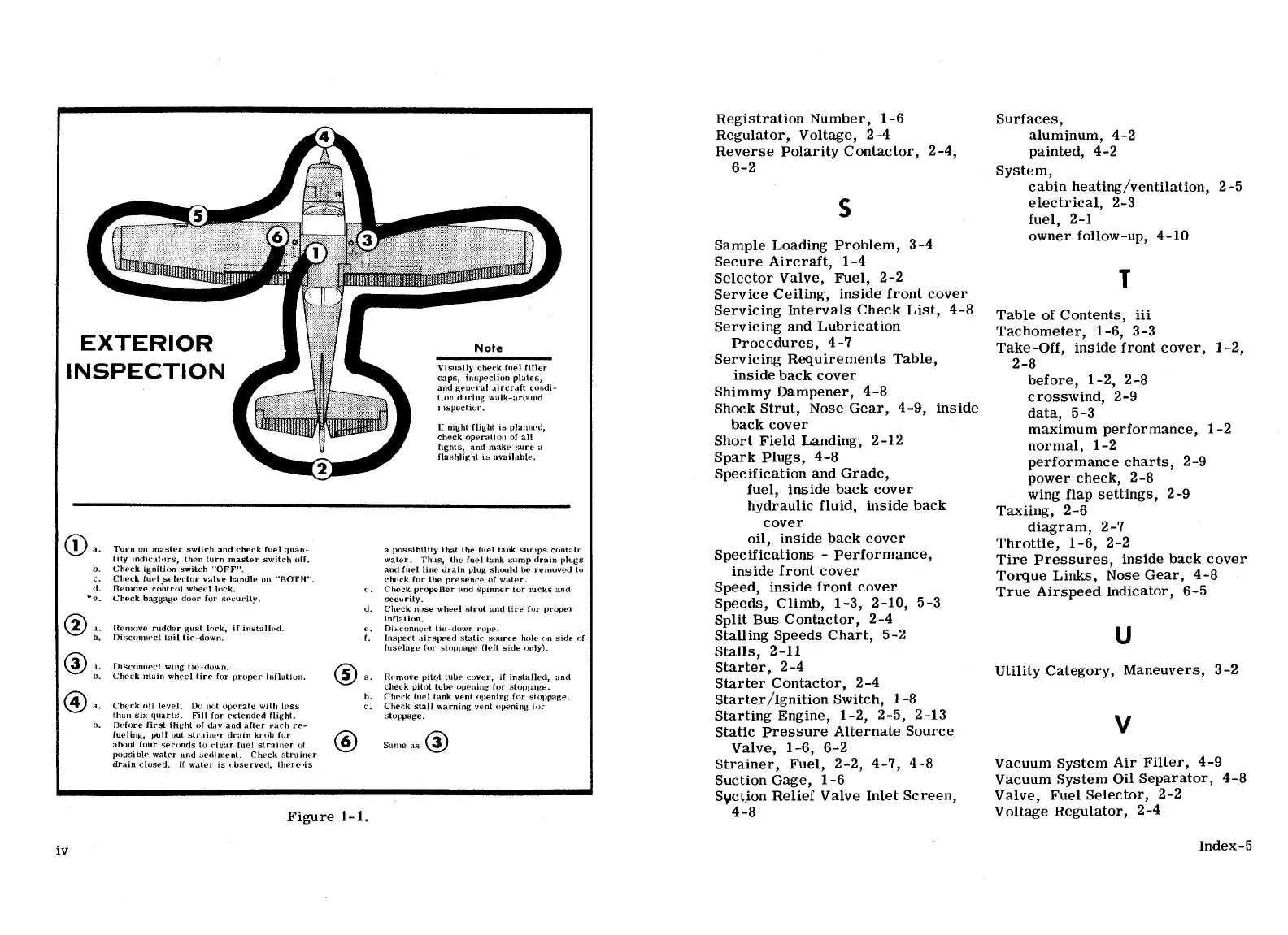
EXTERIOR
Note
Procedures,
4-7
Take-Off,
inside front
cover,
1-2,
Servicing
Requirements Table
2-8
INSPECTION
h
u
aes
inSideback cover
before,
1-2,
2-8
ud ge I
au
condi
Shimmy
Dampener,
4-8
crosswind,
2-9
nspecuen-
Shock Strut, Nose
Gear,
4-9, inside
data,
5-3
1
K night night is
planned,
back
cover
maximum performance
1-2
gÊ,°iiie°iuan
Short
Field
Landing,
2-12
normal,
1-2
flashlight is
available.
Spark
Plugs,
4-8
performance
charts,
2-9
Specification and
Grade,
power
check,
2-8
fuel,
inside back cover
wing
flap
settings,
2-9
hydraulic fluid,
inside
back
Taxiing,
2-6
cover
diagram,
2-7
oil,
inside
back
cover
Throttle
1-6
2-2
a. Turn on master
switch and
check fuel
quan-
a
possibility
that Lhe fuel tank
sumps contain
I
?
Lity
indicators, then turn
master
switch off. waLer.
Thus,
the fuel
tank
sump
drain
plugs
Specifications
-
Performance,
Tire
Pressures,
inside back cover
b. Check ignition switch
"OFF".
and fuel line drain
plug should be removed to
inSide
front cover
c. Check
fuel
selector
valve handle
on "BUTH". check for Lhe presence
of
water.
. .
TOrque
Links,
Nose Gear,
4-8
d. Remove
control wheel lock.
c, Check propeller and sµinner
for
nicks
and
Speed, mside front cover
True Airspeed
Indicator,
6-5
e. Check baggage
door for
security.
d.
seheucrk
ny<>se
wheel strut and
tire for
proper
Speeds,
Climb,
1-3, 2-10,
5-3
inna =-
Split
Bus
Contactor,
2-4
a. Hemove rudder gust
lock,
if
installed.
e. Disconnect
lie-down
rope.
b. Disconnect Lail
tie-down.
f. Inspect airspeed static
source
hole
on side
of
Stalling
Speeds Chart,
5-2
fuselage
for
stoppage
(lefL
side only)
Stalls,
2-11
iLn
e ire
on
proper
innation.
a. Remove puoi tube
cover, U
instaHed,
and
Starter,
2-4
Utility Category,
Maneuvers,
3-2
check pilot tube oµening for
stoppnge.
Starter Contactor,
2-4
a. Check oil
level. Do not operate
with
less s
llanknient oenening
>r stoµpage
Starter/Ignition
Switch,
1-8
than
six
quarts.
Fill
for extended
flight, stoppage.
Starting Engine,
1-2, 2-5,
2-13
h.
I3efore first
flight of day and after
each
re-
fueling,
pull out strainer
drain
knob for
Static
Pressure Alternate
Source
V
about four seconds
to clear fuel
sLrniner of
Same as
Valve
1-6
6-2
possible water and sediment.
Check strainer
i i
drainclosed.
Ifwaterisobserved,there.is
Strainer,
Fuel,
2-2,
4-7,
4-8
VacuumSystemAirFilter,
4-9
Suction Gage,
1-6
Vacuum System
Oil
Separator,
4-8
Syct.ion Relief
Valve
Inlet Screen, Valve,
Fuel
Selector,
2-2
Figure
1-1.
4-8
Voltage
Regulator,
2-4
.
Index-5
1V