29
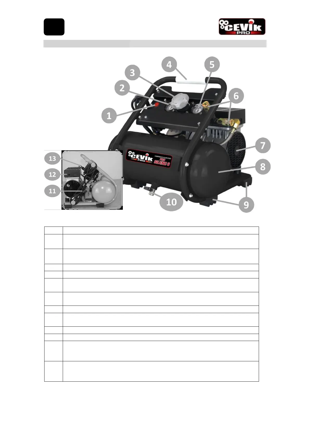
DESCRIPTION OF THE ELEMENTS.
Pressure switch O / F pressure switch to connect and disconnect the compressor.
Tank pressure gauge: Indicates the pressure of the air stored in the tank.
Air pressure regulator: Controls the outlet pressure of the air flow. Turn the regulator
clockwise to increase pressure and counterclockwise to decrease pressure.
Handle: With non-slip rubber that allows an easy and safe movement.
Air outlet pressure gauge: Indicates the outlet pressure selected with the regulator.
Air vents with regulated pressure: With universal quick coupling that allows to connect
a hose in a safe, comfortable and easy way.
Fans: Provide the air flow necessary to keep the compressor at the proper operating
temperature.
Air tank: Stores the air produced by the compressor heads.
Rubber pads: They prevent the compressor from moving and the transmission of
vibrations.
Drain: Allows the air and water tank to be emptied by condensation.
Air filter connection: Ensures impurity-free compressor operation. Starting the
compressor without the air filter installed can cause damage to the inside of the
compressor head.
Safety valve: Relieves the pressure in the tank in the event that it exceeds 8.8 bar. The
valve is a critical element in compressor safety. It must not be manipulated under any
circumstances.