Hardware Setup
7
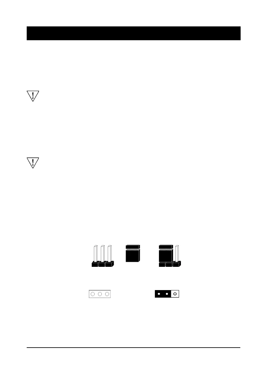
A cap over pin 1 and
pin 2 shorts these pins
Pins SettingCap
A 3-pin jumper
1
1
Figure 2-1Figure 2-1
Figure 2-1Figure 2-1
Figure 2-1
Chapter 2Chapter 2
Chapter 2Chapter 2
Chapter 2
HarHar
HarHar
Har
dd
dd
d
ware Setupware Setup
ware Setupware Setup
ware Setup
If your mainboard has already been installed in your computer you may still need to
refer to this chapter if you plan to upgrade your system's hardware.
Be sure to disconnect the power cable from the power source before performing
any work on your mainboard, i. e. installing a CPU, memory module,
changing a jumper setting, etc. Not doing so may result in electrical shock!
2-1 Introduction to Jumpers
Jumpers are used to select between various operating modes. A jumper consists of
a row of gold colored pins that protrude from the surface of the mainboard. It is
important not to confuse jumpers with connectors or headers.
Putting jumper caps on anything that is not a jumper may result in damaging
your mainboard. Please refer to Section 1-3, Mainboard Layout, for the
location of jumpers on your mainboard.
As indicated in Figure 2-1 below, a cap is used to cover the pins of a jumper, resulting
in shorting those pins that it covers. If the cap is removed from the top of the pins,
the jumper is left "open." The number 1 shown both in the diagram below and in
all multiple pin jumper and header diagrams in this manual indicates the pin designated
with the number 1. The numbering of the remaining pins follows in sequence.