EasyManua.ls Logo

CHAINTECH 7VJL1 - User Manual

CHAINTECH 7VJL1
30 pages
Print Icon
To Next Page IconTo Next Page
Loading...
CHAINTECH
7VJL1
AMD® Socket A
VIA® KT266A + VT8235
ATX Motherboard
User’s Manual
Ver s i o n 1 . 0
Declaration of Conformity
According to 47 CFR, Parts 2 and 15 of the FCC Rules
The following designated product:
EQUIPMENT: MAINBOARD
MODEL NO.: 7VJL1
is a Class B digital device that complies with 47 CFR Parts 2 and 15 of the FCC
Rules. Operation is subject to the following two conditions:
1. This device may not cause harmful interference.
2. This device must accept any interference received, including interference that
may cause undesired operation.
This declaration is given to the manufacturer:
CHAINTECH-EXCEL COMPUTER INC.
4427 Enterprise St. Fremont, CA 94538, U.S.A.
http://www.chaintech-excel.com
Chaintech President: Simon Ho
Signature:
Question and Answer IconNeed help?

Do you have a question about the CHAINTECH 7VJL1 and is the answer not in the manual?

Summary

Chapter 1 Introduction

1-1 Product Specifications

Details CPU, Chipset, Memory, Expansion Slots, Audio, and I/O specifications.

Chapter 1 Introduction

1-3 7 VJL1 Motherboard Diagram

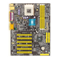
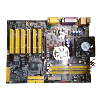
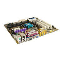
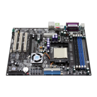
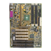
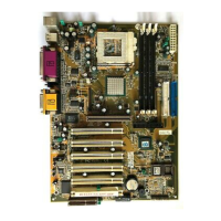
Visual layout of the motherboard with component placements.

1-4 7 VJL1 Motherboard Layout

Labeled diagram illustrating motherboard component locations and connectors.

Chapter 2 Hardware Setup

2-1 Installing a CPU Processor for Socket A

Step-by-step instructions for installing an AMD Socket A CPU.

2-2 Setting Your CPUs Performance

Configuration of CPU speed, FSB frequency, multiplier, and Vcore settings.

Chapter 2 Hardware Setup

2-3 Main Memory Configuration

Instructions and specifications for installing DDR SDRAM modules in DIMM slots.

Chapter 2 Hardware Setup

2-4 Connector and Jumper Reference Chart

A reference table listing all motherboard connectors and jumpers with their functions.

Chapter 2 Hardware Setup

2-5 Connector and Jumper Settings: Power & Floppy

Details for ATX power supply and floppy drive connectors.

Chapter 2 Hardware Setup

2-5 Connector and Jumper Settings: IDE & Fans

Details for IDE hard disk connectors and cooling fan connectors.

2-5 Connector and Jumper Settings: CMOS & FSB Jumpers

Explains crucial jumpers like CMOS Clear (JP1) and FSB Setting (JP3).

Chapter 2 Hardware Setup

2-5 Connector and Jumper Settings: USB & LED Jumpers

Configuration of USB power jumpers (JP5, JP6, JP6A/B) and Green LED jumper (JP23).

Chapter 2 Hardware Setup

2-5 Connector and Jumper Settings: Panel & ROM

Details for ROM SIP jumper (JP30) and front panel connectors (CN1A).

Chapter 2 Hardware Setup

2-5 Connector and Jumper Settings: Audio & Wakeup

Describes connectors for auxiliary audio (CN3), Wake-on-Modem (CN5A), Wake-on-LAN (CN5), and Smart Card Reader (CN7).

Chapter 2 Hardware Setup

2-5 Connector and Jumper Settings: LEDs & I;O

Details for LED (CN17), USB (CN23/23A), Front Audio (CN24), and IR (IR1) connectors.

Chapter 3 BIOS Setup Program

3-1 Standard CMOS Setup

Configuration of system date, time, IDE devices, floppy drive, and video settings.

Chapter 3 BIOS Setup Program

3-2 Advanced BIOS Features

Advanced system settings including virus warning, cache, boot order, and security options.

Chapter 3 BIOS Setup Program

3-3 Advanced Chipset Features

Configuration of DRAM timing, AGP aperture, and PCI bus settings.

Chapter 3 BIOS Setup Program

3-4 Integrated Peripherals

Configuration of onboard devices like IDE, audio, LAN, and Super I/O.

Chapter 3 BIOS Setup Program

VIA Onchip IDE Device Configuration

Settings for IDE channels, prefetch mode, and PIO/UDMA modes.

VIA OnChip PCI Device Configuration

Configuration for onboard AC97 Audio, Modem, LAN, and Boot ROM.

Super IO Device Configuration

Settings for FDC, Serial Ports, Parallel Port, Game Port, and CIR Port.

Chapter 3 BIOS Setup Program

3-5 Power Management Setup

Configuration of system power saving features like ACPI, HDD power down, and suspend modes.

Chapter 3 BIOS Setup Program

3-6 PNP;PCI Configurations

Configuration of Plug and Play (PNP) and PCI device settings, IRQ, and DMA assignments.

3-7 PC Health Status

Monitoring system temperature, voltages, and fan speeds.

Chapter 3 BIOS Setup Program

3-8 Frequency;Voltage Control

Adjusting CPU clock speed, voltages for DIMM, AGP, Chipset, and CPU.

Chapter 3 BIOS Setup Program

CPU Voltage and Clock Ratio Settings

Detailed settings for CPU voltage regulation and clock ratio adjustment.

Loading BIOS Defaults

Options to load fail-safe or optimized default BIOS settings.

3-11 Supervisor Password & User Password Setting

Setting supervisor and user passwords to protect BIOS settings and system access.

Chapter 3 BIOS Setup Program

3-12 Save and Exit Setup

Saving configuration changes and exiting the BIOS setup.

3-13 Exit Without Saving

Exiting the BIOS setup without saving any changes.

Chapter 4 DRIVER Setup

4-1 VIA Service Pack Installation

Guide to installing the VIA Service Pack for system drivers.

Chapter 4 DRIVER Setup

4-2 Audio Driver Installation

Instructions for installing the VIA Audio driver.

Chapter 4 DRIVER Setup

4-3 USB 2.0 Driver Installation

Steps for installing the USB 2.0 driver.

How To Contact CHAINTECH

Regional Contact Information

Contact details organized by geographical regions (Asia, America, UK, etc.).

CHAINTECH 7VJL1 Specifications

General IconGeneral
BrandCHAINTECH
Model7VJL1
CategoryMotherboard
LanguageEnglish

Related product manuals