Chapter 3
31
3.
IDE Primary/Secondary Master/Slave PIO:
The four IDE PIO (programmed Input/Output) fields let you set a PIO mode (0-4)
for each IDE device that the internal PCI IDE interface supports. Modes 0 through 4
provide successively increased performance. In Auto mode, the system automatically
determines the best mode for each device.
4.
IDE Primary/Secondary Master/Slave UDMA:
Ultra DMA implementation is possible only if your IDE device supports it and your
operating environment contains a DMA driver. If both your hard drive and software
support Ultra DMA, select [
Auto
] to enable BIOS support.
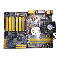
VIA OnChip PCI Device:
This section provides information for setting onboard device. By choosing the
Integrated Peripherals option from the CMOS Setup Utility menu (Figure 3-5), the
screen below is displayed. This sample screen contains the manufacturer's default
values for the motherboard
Press [Enter] to enter the sub-menu, which contains the following items for advanced
control:
1.
VIA AC97 Audio:
This feature allows you to disable the on-board AC97 audio function.
2.
VIA MC97 Modem:
This item allows you to disable the chipset’s feature to support MC97 Modem.
3.
VIA OnChip LAN
This feature allows you to enable the OnChip LAN function.
4.
Onboard Lan Boot ROM
This feature allows you to boot up the system through a LAN function.
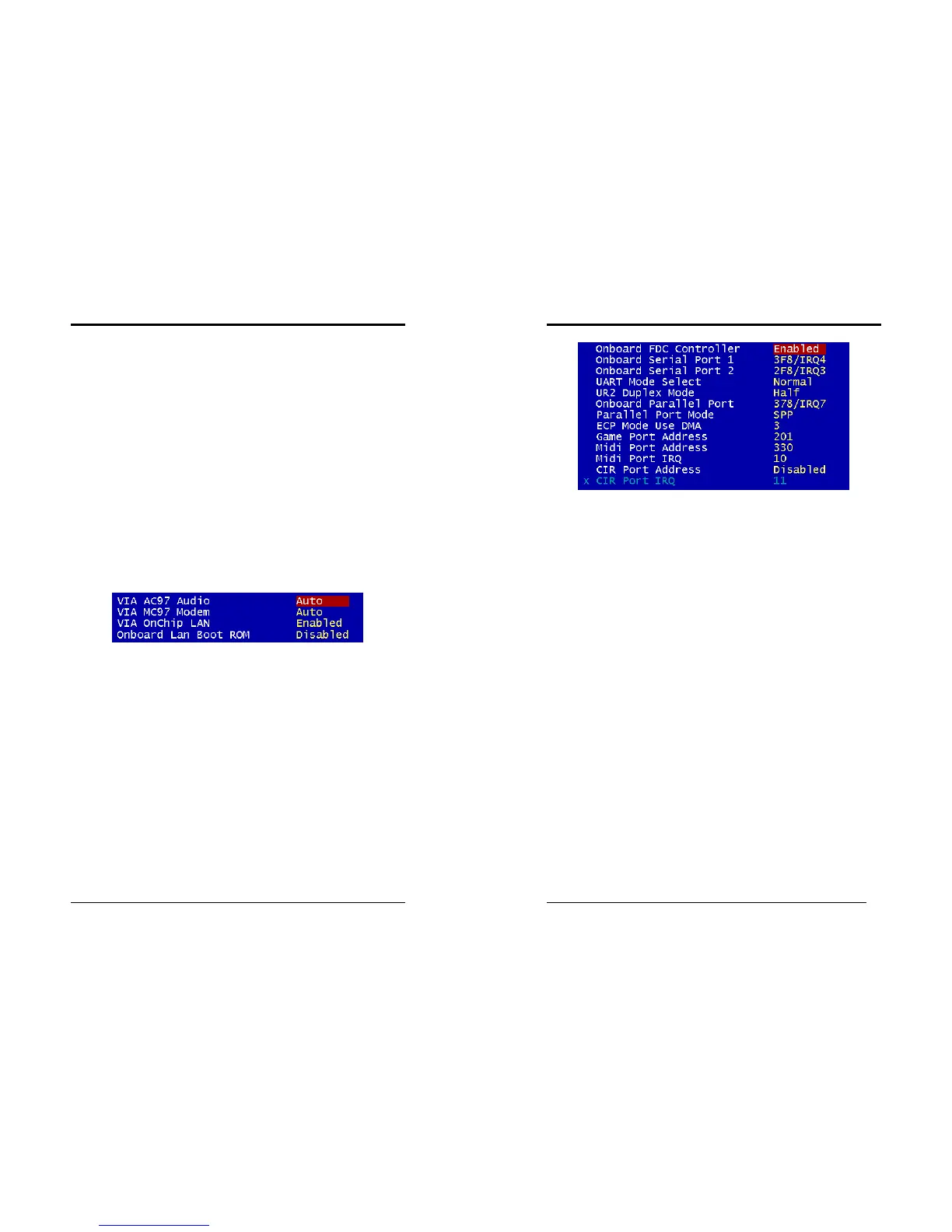
Super IO Device:
This section provides information on setting Super I/O device. By choosing the
Integrated Peripherals option from the CMOS Setup Utility menu (Figure 3-5), the
screen below is displayed. This sample screen contains the manufacturer's default
values for the motherboard.
Press [Enter] to enter the sub-menu, which contains the following items for advanced
control:
Chapter 3
32
1.
Onboard FDC Controller:
Select Enabled if your system has a floppy disk controller (FDC) installed on the
system board and you wish to use it. If you install an add-in FDC or the system has
no floppy drive, select Disabled in this field.
2.
Onboard Serial Port 1/2:
Select an address and corresponding interrupt for the first and second serial ports.
Available options are [
3F8/IRQ4
], [
2E8/IRQ3
], [
3E8/IRQ4
], [
2F8/IRQ3
],
[
Disabled
], and [
Auto
].
3.
UART Mode Select:
This function allows you to select an operating mode for the second serial port.
Available options are [
Normal
], [
IRDA
], [
ASKIR
] and [
SCR
].
4.
Onboard Parallel Port:
Select a logical LPT port address and corresponding interrupt for the physical
parallel port.
5.
Parallel Port Mode:
Select an operating mode for the onboard parallel (printer) port. Select SPP unless
you are certain your hardware and software support one of the other available
modes.
6.
ECP Mode Use DMA:
This item automatically specifies a DMA channel
1
or
3
for the parallel port when it
is set to [
EPP
] or [
ECP+EPP
] mode.
7.
Game Port Address:
This item disables or assigns the address of the Game port. Available options are
[
Disable
], [
201
] and [
209
].
8.
Mini Port Address:
This item disables or assigns the address of the Midi port. Available options are
[
Disable
], [
300
] and [
330
].