Chapter 2
9
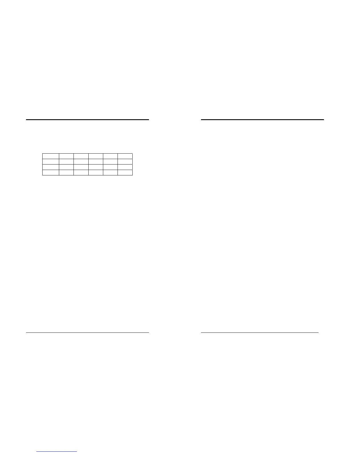
DIMM Module Combination
Install at least one DIMM module on the slots. You can install either single- or
double-sided modules in any order to meet your own needs. Memory modules can
be installed in any combination as follows:
Location 64 MB 128 MB 256 MB 512 MB 1.0 GB
DDR 1 X X X X X
DDR 2 X X X X X
DDR 3 X X X X X
To install your DDR Modules please follow the following steps:
1. Unlock a DIMM socket by pressing the retaining clips outward. The DDR
Modules has only one notch at the center of module. The DDR module will only
fit in the right position.
2. Insert the DDR Module vertically into the DIMM slot, with the correct alignment.
Then push it in until the golden finger on the memory module is deeply inserted
into the socket.
3. The plastic clip on each side of the DIMM slot will automatically close to hold the
DDR Modules in place.
Chapter 2
10
2-4 Connector and Jumper Reference Chart
Jump Connector Function Page
PW 1/2 ATX Power Supply Connector 11
FD1 Floppy Connector 12
IDE 1/2 IDE Hard-Disk Connector 13
FAN 1/2/3 CPU/ System / Case FAN Connector (12V) 13
JP1 CMOS Clear Jumper 14
JP3 CPU Front Side Bus setting 14
JP5 Keyboard Power on Function Jumper 15
JP6 Disable/Enable USB 0/1 Device Power ON Jumper 15
JP6A /B Disable/Enable USB 2/3,4/5 Device Power ON Jumper 16
JP23 Green LED Mode Jumper 16
JP30 ROM SIP 17
CN1A Front Panel (Power / Rest / SPK…etc.) Connector 17
CN2 /2A CD-ROM Audio-in Connector 18
CN3 Auxiliary Audio-in Connector 19
CN5 Wake on LAN Connector 19
CN5A Wake on Modem Connector 20
CN7 Smart Card Reader Connector 20
CN17 Blue LED Connector (5V) 21
CN23 /23A USB Connector for USB 2/3 and 4/5 21
CN24 Front Audio Connector 22
IR1 IR Connector 22