Chapter 2
13
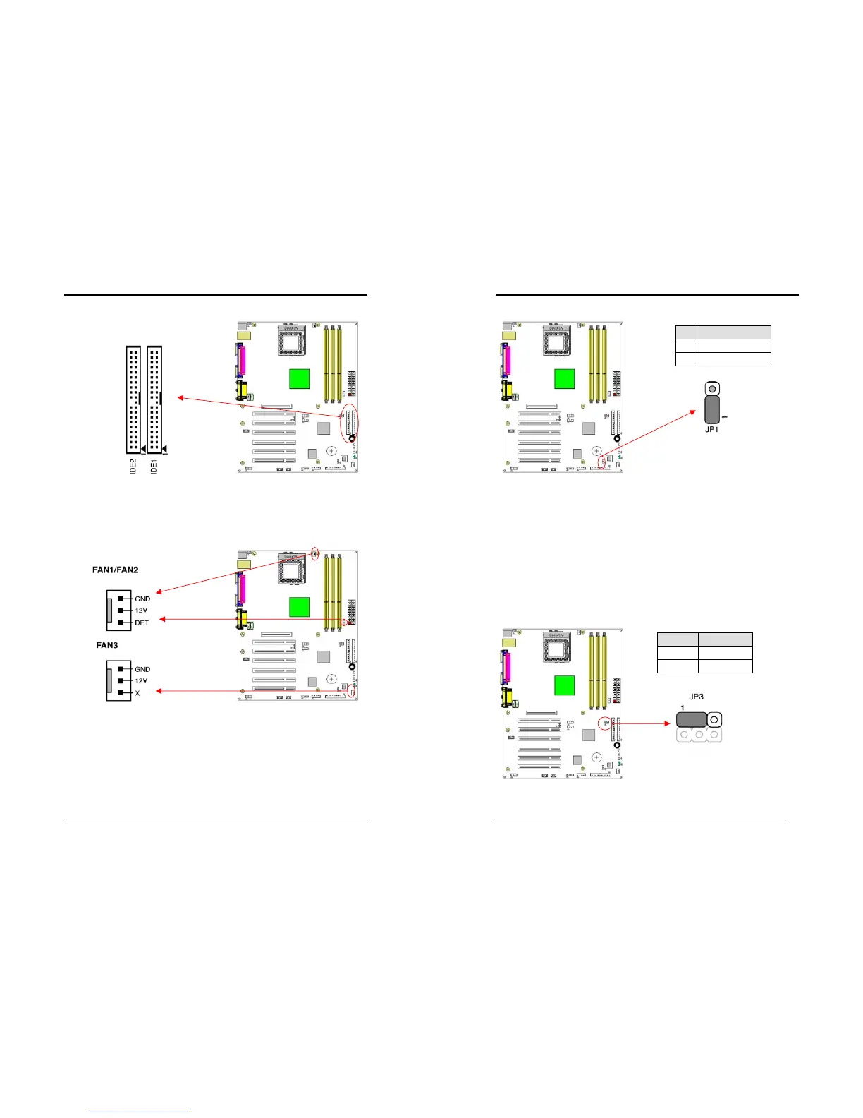
IDE 1/2 (IDE Hard-Disk Connector)
This connector is used for connecting 40 pins of ATAPI devices.
IDE 1 only connects two IDE devices. (Primary Master/Slave)
IDE 2 only connects two IDE devices. (Secondary Master/Slave)
FAN1/FAN2/FAN3 (CPU/System/Case Cooling Fan Connectors [12V]):
The board's management extension hardware is able to detect the CPU and system
fan speed in rpm (revolutions per minute). The wiring and plug may vary depending
on the manufacturer. On standard fans, the red is positive (+12V), the black is
ground, and the yellow wire is the rotation signal.
Chapter 2
14
JP1 (CMOS Clear Jumper):
There is a CMOS RAM on board that has a power supply from external battery to
keep the data and system configuration. To clear the contents of the CMOS, please
follow the steps below.
1. Disconnect the system power supply from the power source.
2. Set the jumper cap at location [
2-3
] for <
5 seconds
>, and then set it back to the
default position.
3. Connect the system's power and then start the system.
4. Enter BIOS's CMOS Setup Utility and choose Load Setup Defaults. Type [
Y
] and
then press [
Enter
] to continue.
5. Set the system configuration in the Standard CMOS Setup menu.
JP3 (CPU Front Side Bus setting)
This function allows you to set the CPU’s Front Side Bus, the default setting is at
pin [1-2], which is FSB 100MHz. Set the cap at [2-3] to force the FSB at 133 MHz.
Pin Definition
1-2 Normal (default)
2-3 Clear CMOS Data
Pin Definition
1-2 FSB 100 MHz
2-3 FSB 133 MHz