Chapter 2
15
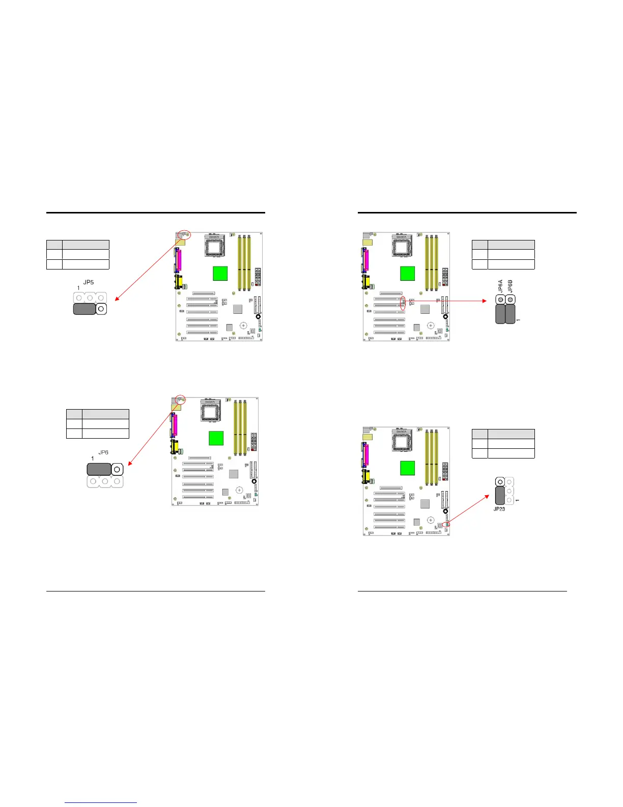
JP5 (Keyboard Power On Function Jumper):
This board can be turned on by the PS / 2 keyboard (hot key). To use this function,
select a hot key of your choice at the PS2KB Wakeup option under Wake Up Events
in the BIOS's Power On Management screen. You must also set this jumper's cap to
pins 2-3 to use this function.
JP6 (Enable/Disable USB 0/1 Device Power ON Jumper)
This motherboard is can be turned on by a USB keyboard hot key or a USB mouse
click. To use this function, select a hot key of your choice at the USB KB Power
Wake-up From S3 option under Wake Up Events in the BIOS's Power On
Management screen. You must also set this jumper's cap to pins
2-3
to use this
function.
Pin Definition
1-2 Disable (default)
2-3 Enable
Pin Definition
1-2 Disable (default)
2-3 Enable
Chapter 2
16
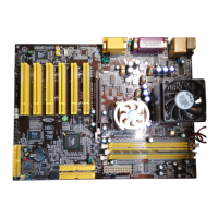
JP6A/B (Enable/Disable USB 0/1, 2/3 Device Power ON Jumper)
This motherboard is can be turned on by a USB keyboard hot key or a USB mouse
click. To use this function, select a hot key of your choice at the USB KB Power
Wake-up From S3 option under Wake Up Events in the BIOS's Power On
Management screen. You must also set this jumper's cap to pins
2-3
to use this
function.
JP23 (Green LED Mode Jumper):
This motherboard provides a Green LED flash Jumper. This cap is to setup Green
LED flash mode.
Pin Definition
1-2 Disable (default)
2-3 Enable
Pin Definition
1-2 Normal (default)
2-3 Reserve