Chapter 2
21
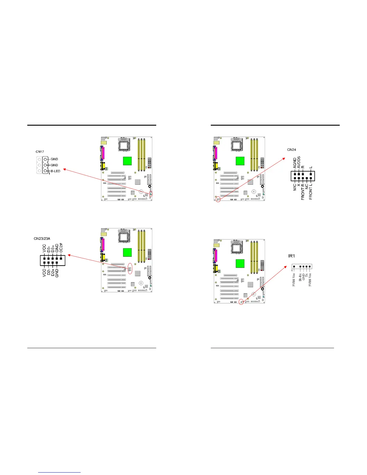
CN17 (Blue LED Connector):
These features work entirely the same as the power indicator LED, both shows the
system’s power status. The only difference is that this one is blue while the other is
red LED.
CN23/23A (USB Connector for USB 2/3 and 4/5)
If you want to use a USB Keyboard, you must enable the USB keyboard support
function in BIOS's Integrated Peripherals menu (See Section 3). This board contains
a USB Host controller and includes a root hub connector for optional USB Adaptor
(USB 2/3 and 4/5).
Chapter 2
22
CN24 (Front Audio Connector):
This connector give you the option of a front panel audio jack cable ext. to be plug
into a special custom designed system case. Simply remove the two jumper caps at
pin [5-6] and [9-10] then plug it into the (optional) cable ext. connector. Pin [5-6]
and [9-10] are shorted (default) to enable the back panel audio function.
IR 1 (IR Connector):
Select a UART Mode in BIOS's Integrated Peripherals menu the UART port to
support IR function. (See section 3)