7 . ACCESSORIES AND OPTIONS
7.79
Challenger MT500B EU
7
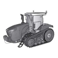
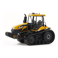
When the linkage and depth wheel controls are actuated,
the position values vary (Fig. 190):
43. Linkage high position value
44. Plough depth wheel high position value
• Memorise the high positions by pressing the key «
1
.
The high position values are displayed in the greyed
boxes and are memorised.
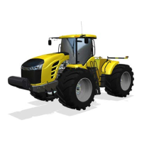
Memorising the low position:
• Place the linkage and depth wheel in working position
(plough horizontal Fig. 191) using the following controls:
- the rear linkage control and low position limiter,
- the plough depth wheel spool valve control.
NOTE: If possible, place the depth wheel cylinder in the
low mechanical stop position.
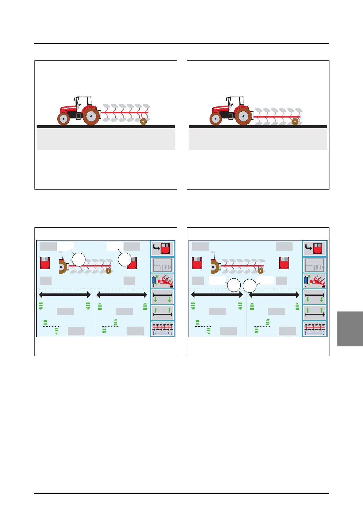
When the linkage and depth wheel controls are actuated,
the position values in the white boxes vary (Fig. 192):
45. Linkage low position value
46. Plough depth wheel low position value
• Memorise the low positions by pressing the key «
1
. The
low position values are displayed in the greyed boxes
and are memorised.
Z3A-963-08-04
Fig. 189
100%100%
100%
0%
0%
0% 0%
100%
6.0
6.0
100%
100%
6.0
6.0
1920
42.0
68% 79%
Z3A-964-08-04-B
Fig. 190
m
m
m
m
43 44
Z3A-965-08-04
Fig. 191
79%68%
100%
0%
0%
100%
6.0
6.0
100%
100%
6.0
6.0
1920
42.0
68% 79%
27% 32%
Z3A-966-08-04-B
Fig. 192
45
46
m
m
m
m
 Loading...