7 . ACCESSORIES AND OPTIONS
7.90
Challenger MT500B EU
On furrow end (return run):
As soon as the linkage lifting control is actuated, the tractor
icon is positioned at the top of the field (transport position)
(Fig. 224).
The length (88 Fig. 224) has become positive again. Thus,
a complete run has been performed.
If for any reason the linkage control must be activated
while using the POINTS menu, the sequence of actions is
no longer synchronised. In other words, the tractor icon is
not positioned correctly in the POINTS menu in relation to
reality. To correct the tractor icon position, press the
key
«
3
when the window (Fig. 224) is open. Each time this
key is pressed, the tractor icon is moved.
NOTE: This menu can only be used with a single DUAL
CONTROL.
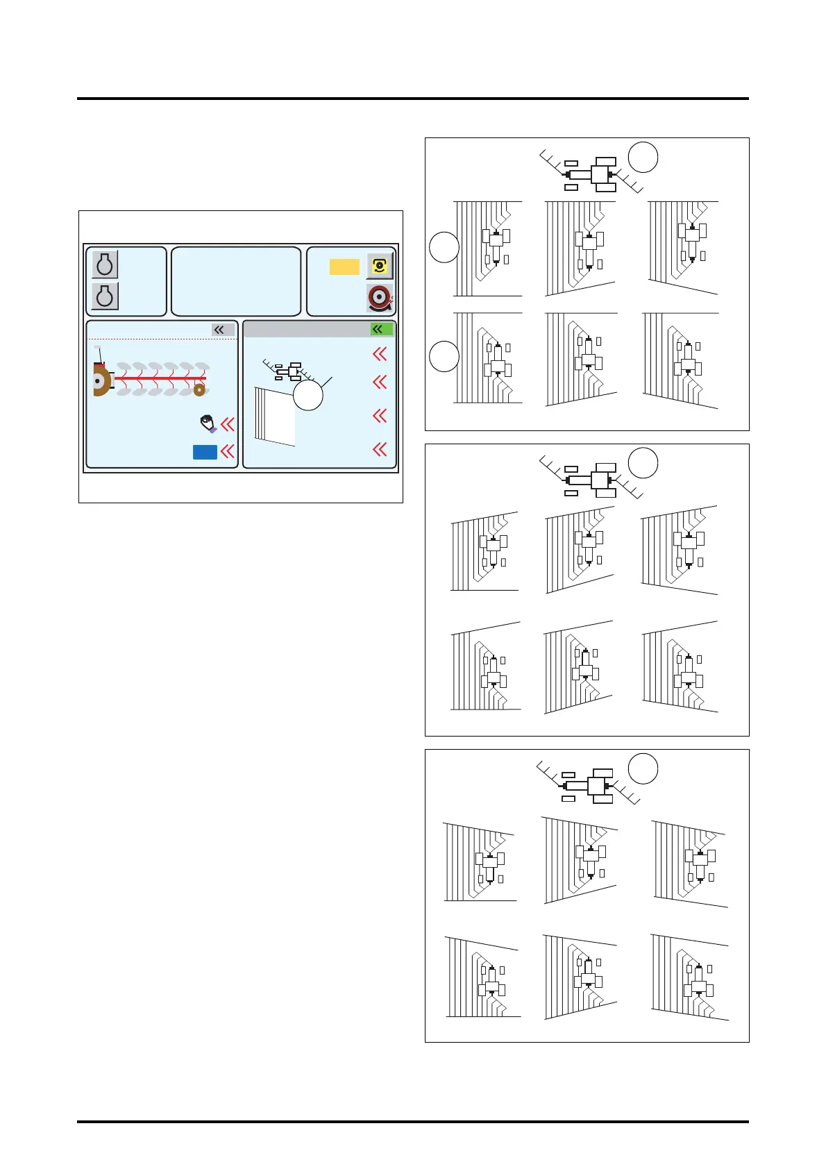
7.14.1.3 - Diagram identification:
• Method for a figure (Fig. 225)
In each figure, various field shapes are represented. The
tractor icon (89 Fig. 225, Fig. 226 and Fig. 227)is in trans-
port position at the top of each window.
- Select the diagram best adapted to your field. The three
top diagrams represent the outward run (90) and the
three bottom diagrams represent the return run (91).
- Observe the point length sign (plus (+), minus (-) or zero
(0)) of the diagram you are interested in.
- Set the value corresponding to your field in the points
menu (Fig. 216).
IMPORTANT: To adjust the point lengths, the three top
diagrams must be considered (90). The bottom dia-
grams representing the return trip show that the plus
(+), minus (-) or zero (0) values are reversed as soon as
the half turn has been made.
NOTE: These three figures (Fig. 225, Fig. 226 and Fig.
227) apply in cases where the ploughed earth is tilled to
the right of the tractor on the outward run. If the
A
B
1000
2000
790
5.3
10% M
5%
540
1
2000
1.4
3.2
Reset
Syncr
2
ON
Z3A-1369-12-04
Fig. 224
REAR DUAL CTRL POINTS
m
m
RPM
KPH
88
0
0
0
0
+
-
000
0
-
+
Z3A-1017-08-04
Fig. 225
89
90
91
-- -
+
+
+
0+-
0
-
+
Z3A-1018-09-04
Fig. 226
89
+++
0
+
-
-
-
-
0
-
+
Z3A-1019-09-04
Fig. 227
89
 Loading...