Do you have a question about the Chamberlain LiftMaster CB1 and is the answer not in the manual?
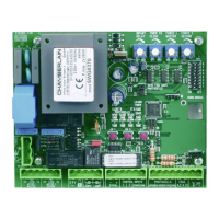
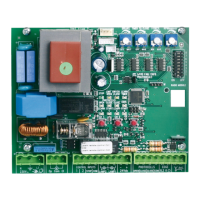
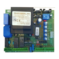
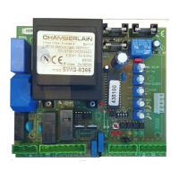
Details connections for Neutral (N), Protective Earth (PE), and Live (L1) 230V mains power supply.
Describes connections for first (M1) and second (M2) motors, including direction, neutral, and capacitor.
Details connections for infrared light barrier photocells (NC) and COM terminals.
Explains connections for the emergency stop function using COM and NC terminals.
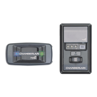
Details IR sensor installation at knee height, transmitter/receiver setup, and connection options.
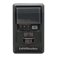
Explains how an emergency stop switch can disable the installation by interrupting wing movement.
Describes operation requiring continuous signal transmission for gate movement, stopping on signal loss.
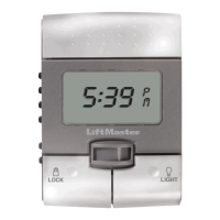
Controls automatic closing function and pause time adjustment when set to ON.
Enables Dead Man's operating mode when set to ON, requiring continuous signal.
Determines light barrier behavior: stops gate (ON) or reverses direction (OFF) when closing.
Adjusts the operating force for each wing (M1/M2) separately for fine-tuning gate movement.
Sets the time the gate/door remains open before automatically closing, adjustable from 8-200 seconds.
Sets the maximum running time for gate/door wings to ensure reliable end-position reach.
Provides a step-by-step guide for initial setup, including connecting safety inputs and setting parameters.
| Model | CB1 |
|---|---|
| Type | Control Panel |
| Compatibility | LiftMaster |
| Power Source | Battery |
| Security | Rolling code technology |
| Mounting | Wall-mounted |