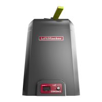
The LiftMaster MADCBB, MATDCBB, MASDCBB, & MASTDCBB are heavy-duty DC barrier gate operators designed for vehicular gate applications. These operators come with an owner's manual and include a radio receiver.
Function Description:
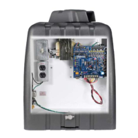
The primary function of these devices is to control vehicular barrier gates. They feature a full-service controller with eight inputs and LED indicators for various functions like loops, card reader, and radio. The operator's arm direction is reversible for right or left-handed operation. An Instant Reverse Device (IRD) monitors for obstructions during motion, ensuring safety. In case of AC power failure, the gate will automatically open (fail-safe). The raise gate input memory allows the operator to memorize multiple vehicles, making it ideal for barcode scanners and AVI systems. It can stop the arm in close travel if tailgating is sensed at the close loop and features an anti-tailgate alarm that triggers a K1 relay to activate a warning device. The SAMS (Sequence Access Management System) with "memory" allows the Mega Arm to open a slide/swing gate first, then raise the arm. Dynamic motor braking is incorporated to preserve arm positioning. The direct drive gear reducer design minimizes parts that could fail, and the state-of-the-art MOSFET motor drive technology eliminates the need for contactors or relays. It offers soft start and stop in open and close travel motions. Instead of traditional limit switches, it uses magnetic (Hall Effect) sensors to monitor arm position. A maximum run timer with anti-tamper protection is included for the closing direction. Each operator can be configured as a primary or second operator, and LED diagnostics simplify troubleshooting. An adjustable Timer-To-Close function with on/off selection is available, and all inputs are protected against transient voltage.
Important Technical Specifications:
- Motor: High torque 24-volt Permanent Magnet DC motor.
- Power Input: Capable of being powered from 120 or 230 Vac, or UL Listed Class 2 Solar Power.
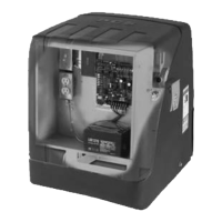
- Battery Backup: Built-in battery run provides inherent 24 Vdc backup power with regulated 24 Vdc for accessories. The system uses two LiftMaster 12 Vdc 7AH batteries (Part # MBAT), which are included and must be connected for proper operation.
- Accessory Power: On 120 Vac installations, an unswitched duplex outlet provides a convenient supply for 120 Vac accessories.
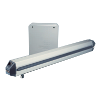
- Barrier Arm: Designed for a break-away mount for a 12-15 foot x 3 inch tubular aluminum barrier arm.
- Construction: All rust-proof aluminum construction with a white powder coat baked on enamel. Molded Polyethylene UV stabilized cover requires no wax or paint (excluding towers).
- Heater Option: A heater option MUST be used if the temperature is 30°F or below. This option is available for 120 Vac operators ONLY.
- Wiring: Uses UL approved 14AWG (or larger) 600 volt insulated wire only.
- Radio Receiver: Included.
Usage Features:
- Installation: The manual provides detailed instructions for installing the concrete pad for both pedestal and tower models, including dimensions and conduit requirements. It also covers attaching the operator to the concrete pad using wedge anchors and installing the barrier arm.
- Wiring: Clear instructions for 120 VAC and 230 VAC power wiring, emphasizing safety precautions like disconnecting power before servicing. Detailed explanations for inputs on the J5 terminal strip, including terminal functions like OPEN, AUXILIARY OPEN, SAFETY, CLOSE, BACK-AWAY (FREE EXIT), SHADOW (SAMS), and COMMON.
- Accessory and Relay Connections: Instructions for connecting auxiliary devices to the K1 Relay and J1 terminal strip.
- Primary/Second Wiring: Guidance on configuring operators as primary or secondary, including wiring diagrams for IRD obstruction signal connections.
- Radio Receiver Installation: Steps for installing the radio receiver, setting up security codes, and programming the remote control.
- DIP Switches (S1 & S2):
- S1-1 to S1-4 (Fast Run Timer): Adjusts the full-speed run time in 1/8 second increments.
- S1-5 (Single Button Function): Activates single-button open/close functionality.
- S1-6 (Clutch Option): Allows the barrier arm to automatically CLOSE if manually forced UP (OPEN).
- S1-7 (Handing the Barrier Arm): Controls the motor wiring for right-hand or left-hand operation.
- S1-8 (K1 Relay Optional): Configures K1 relay activation during the OPEN cycle or briefly until the OPEN LIMIT (OLS) is reached.
- S2-1 to S2-5 (Timer-To-Close): Sets the period of time the gate remains open after reaching the OPEN position.
- S2-6 (Multiple Vehicle Memory): Allows the operator to remain OPEN until a pre-authorized number of vehicles pass.
- S2-7 (Auto Close): Enables automatic closing after a set amount of time.
- S2-8 (Fail Safe - Auto Open on AC Power Failure): Ensures the barrier arm automatically opens and remains open during AC power failure.
- IRD Adjustment: Instructions for adjusting the Instant Reverse Device (IRD) sensitivity to detect obstructions.
- Suggested Loop Sensor Locations: Diagrams and recommendations for optimal placement of loop sensors for various scenarios like back-away loop, free exit, and entry with access control.
- Sequence Access Management System (SAMS): Detailed explanation of SAMS functionality, including wiring and operation with the K1 relay.
Maintenance Features:
- Maintenance Schedule: A chart outlining recommended maintenance intervals (every 3, 6, 12, and 24 months) for fasteners, bearings, shafts, and battery replacement.
- General Service: Instructions for adjusting belt tension and checking battery voltage (27.5 +0.05, -0 Vdc disconnected).
- Shear Pin Replacement: Detailed steps for replacing a sheared tapered pin in the output shaft, emphasizing the correct pin type and warning against using a bolt as a temporary fix.
- Battery Maintenance/Testing: Batteries are maintenance-free but should be replaced every two years. Automatic battery testing is conducted, and manual testing instructions are available.
- Battery Disposal: Replaced batteries must be treated as hazardous waste and disposed of according to regulations.
- Troubleshooting: A comprehensive section with flowcharts for diagnosing issues like "Gate Not Operating" and "Battery Checkout." It includes checks for LED indicators (HBEAT, BAT LO, AC PWR), DIP switch settings, fuse checks, and IRD functionality.
- Repair Parts: Lists of part numbers and descriptions for various components, including the controller, motor, batteries, arm bracket, and different types of barrier arms.
- Accessories: A list of available accessories such as remote controls (single, 3-button, 4-button), 24 VDC loop detector, wiring harness, heater kit, K1 relay output option, aluminum gate arms, articulating PVC (folding) arm, and SAMS kit.
The manual includes prominent WARNING and CAUTION labels throughout, emphasizing the importance of reading and understanding all safety instructions. Key warnings include:
- Disconnecting all electric power before performing any maintenance.
- Avoiding serious injury or death from electrocution or moving components.
- Ensuring proper installation of safety devices like photo eyes and loops.
- Never allowing children to play near or operate the gate.
- Using only UL approved wire and ensuring proper grounding.
- Following all wiring diagrams and specifications to prevent damage or injury.
- The product may expose users to chemicals known to cause cancer or birth defects (California Proposition 65 warning).