Do you have a question about the Chameleon Antenna CHA EMCOMM II V2 and is the answer not in the manual?
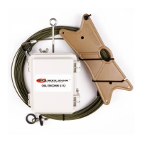
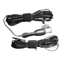
Identifies key parts including the Matching Transformer, Antenna Wire, Isolation Loops, Carabiner, and Wire Connector.
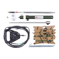
Details the Line Winder, UHF Socket, Top/Bottom Transformer Connections, and Transformer Eyebolt.
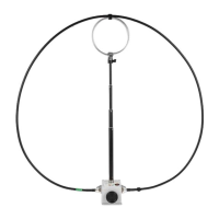
Special configuration for good NVIS propagation on lower frequencies. Omnidirectional.
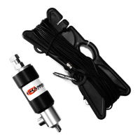
Broadband short to medium range HF antenna for ground and sky wave propagation.
Broadband antenna for short to medium range HF, favors horizontal end, good for ground waves.
The Chameleon Antenna™ Portable High Frequency (HF) Antenna (CHA EMCOMM II V2) is a versatile and dependable antenna system designed for both backup emergency HF systems and permanent installations. It is engineered to provide reliable local, regional, national, and international voice and data communication capabilities, particularly suitable for undeveloped areas or regions where telecommunications infrastructure may be damaged. The antenna's integral broadband impedance matching network transformer allows for wide-range antenna tuning, operating across a broad spectrum from 1.8 to 54 MHz, encompassing the 160m to 6m amateur bands, without requiring adjustments when used with a wide-range antenna tuner or coupler.
The CHA EMCOMM II V2 is a robust solution for various organizations, including military, government agencies, non-governmental organizations (NGOs), Military Affiliate Radio System (MARS), Civil Air Patrol (CAP), Amateur Radio Emergency Service (ARES) / Radio Amateur Civil Emergency Service (RACES), Salvation Army Team Emergency Radio Network (SATERN), and First Responders. Its design also makes it an ideal choice for amateur radio enthusiasts living in apartments, condominiums, or developments with homeowner's associations, deed restrictions, or CCRs (Covenants, Conditions & Restrictions), where stealth and minimal visual impact are often desired.
A key feature of the CHA EMCOMM II V2 is its configurability, allowing it to facilitate Near-Vertical Incident Skywave (NVIS) communication. This capability is crucial for filling the "skip zone" gap between ground wave and skywave propagation, enabling communication over short to medium distances (typically 40 to 300 miles) that are often difficult to cover with traditional HF skywave. The antenna is also totally waterproof, ensuring durability and reliability in various environmental conditions. While it does not strictly require a ground plane, its performance can be enhanced with one, for which a ground terminal is provided.
The antenna system comprises several components: a Matching Transformer, a 60-foot insulated Antenna Wire, Isolation Loops (circular insulators) permanently attached to the ends and middle of the Antenna Wire, a removable pear-shaped stainless steel Carabiner with a spring-loaded gate, and a Wire Connector at the end of the Antenna Wire for connection to the Matching Transformer. Other components include a Line Winder for storing the Antenna Wire, a UHF Socket (SO-239) on the Matching Transformer for coaxial cable connection, Top and Bottom Transformer Connections, and a Transformer Eyebolt for mounting.
The CHA EMCOMM II V2 can be deployed in multiple configurations, each offering unique performance characteristics. The manual describes three primary configurations: Horizontal NVIS, Sloping Wire, and Inverted "L."
The Horizontal NVIS configuration is specifically designed for good NVIS propagation on lower frequencies (typically below 10 MHz). It is predominantly omnidirectional and also provides medium-range skywave propagation on frequencies above 10 MHz. This setup requires two supports to raise the Matching Transformer and the end of the Antenna Wire to a height of 10-12 feet, with the supports approximately 60 feet apart. While higher or lower heights can be used, they may reduce NVIS performance. A counterpoise wire of 50-55 feet is recommended, or alternatively, a coaxial cable of 25-100 feet can serve as the counterpoise.
The Sloping Wire configuration is a broadband short-to-medium range HF antenna, providing acceptable ground wave and skywave propagation. It is primarily omnidirectional, becoming slightly bidirectional towards both ends as the frequency increases. This configuration requires one support, ideally mounted at a height of 25-40 feet for optimal performance. A counterpoise wire of 20-40 feet is recommended, or a coaxial cable of 25-100 feet can be used as the counterpoise. An alternative, the "Half Sloper," involves attaching the antenna to a metal tower and feeding it from the top.
The Inverted "L" configuration is another broadband short-to-medium range HF antenna. It tends to be unidirectional, favoring the horizontal end of the antenna. This setup is effective for ground wave communication during the daytime on frequencies between 1.8-4.0 MHz without relying on skywave propagation. It requires two supports, ideally mounted at a height of 25 feet for best performance, though good performance can still be achieved at 10-20 feet, and it is usable as low as three feet. A counterpoise wire of 20-40 feet is recommended, or a coaxial cable of 25-100 feet can serve as the counterpoise.
The deployment process for each configuration involves site selection, connecting the Matching Transformer, raising the antenna, and extending the counterpoise (if used). For Horizontal NVIS:
For Sloping Wire:
For Inverted "L":
The manual outlines a clear recovery procedure for disassembling and storing the CHA EMCOMM II V2:
The manual provides a systematic troubleshooting guide to address common issues:
The CHA EMCOMM II V2 is designed for ease of use and durability, making it a reliable choice for critical communication needs.
| Impedance | 50 Ohms |
|---|---|
| Connector | SO-239 |
| Operating Temperature | -40°C to +85°C |
| Power Rating | 100W PEP |
| VSWR | 1.5:1 |
| Material | Fiberglass |