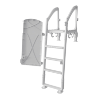
ACM-124S
Designed to be used with ACM-123 steps.
Conçue à être utilisé avec l’escalier ACM-123.
Hardware • Jeu de pièces
Champlain Plastics Inc.
87 Pillsbury Road
Rouses Point, NY 12979
(INS-1124S-rev4)
P1 P2 P3
x 1x 1 x 2
P4
x 1
P5
x 1
x 2 x 2 x 2 x 2
!
x 4 x 4
" #
x 4
$% & '
By/Par : Champlain Plastics Inc.
87 Pillsbury Road, Rouses Point, NY 12979 INS-1124S-rev4
ACM-124S
A
A
IMPORTANT SAFETY INSTRUCTIONS
CAUTION: To prevent damage to the ladder and to minimize
risk of injury follow these instructions carefully.
• Install ladder on a solid base.
•
For ENTRY/EXIT of pool, FACE THE LADDER AT ALL TIMES.
This ladder must be used only to enter and exit the pool. Any
other use could damage the ladder and pool structure.
• NO JUMPING. NO DIVING.
• To prevent entrapment or drowning, do not swim through,
behind or around the ladder.
• Door must be locked at all times
WARNING: The space between the inner pool wall
and the ladder should be no more than 2" to prevent
entrapment between ladder and pool wall.
NOTE: This ladder is designed and manufactured for above
ground pools which are 48", 52" or 54" in height.
The ladder must be removed from the pool and stored in a
dry place for the winter.
NOTES IMPORTANTES DE SÉCURITÉ
ATTENTION : Afin d'éviter d'endommager l'échelle et pour
minimiser les risques de blessures, respecter attentivement
les indications suivantes.
• Installer l'échelle sur une base solide.
• Pour ENTRER/SORTIR de la piscine, TOUJOURS SE
PLACER FACE À L'ECHELLE. Cette échelle doit être utilisée
seulement pour entrer et sortir de la piscine. Toute autre
utilisation pourrait endommager l'échelle et la structure de la
piscine.
• NE PAS SAUTER. NE PAS PLONGER.
• Ne pas nager à travers, derrière ou autour de l'échelle afin
d'éviter d'y demeurer coincée et de se noyer.
• La porte doit être position verrouillée en tout temps.
AVERTISSEMENT : L'espace entre la paroi intérieure de la
piscine et l'échelle ne doit pas excéder 2" afin d'éviter qu'une
personne n'y demeure coincée lors de la baignade.
NOTE : Cette échelle est conçue et fabriquée pour convenir
aux piscines hors terre d'une hauteur de 48", 52" ou 54".
L'échelle doit être sorti de la piscine et remisé dans un
endroit sec pour l'hiver.
x 1 x 8
( )
16 x 2 17 x 2 18 x 2 19 x 4
20 x 4 21 x 1 22 x 2 23 x 2
17
16 19
20
18
21
22
23
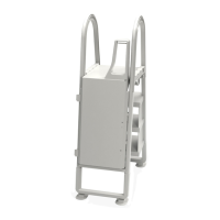
ÉTAPE 8
ATTENTION
Le muret est installé sur
l'extérieur de la piscine.
Attacher le muret protecteur
(14) à la section de l'échelle
avec 4 vis (15).
INSTALLATION
DE LA PORTE
ATTENTION
La porte est installée sur
l'extérieur de la piscine.
Attacher la porte au cadre de
l'échelle en utilisant 2 cales
(16), 2 vis longues (17) pour
la penture du haut, 2 vis
courtes (18) pour la penture
du bas, 4 rondelles (19) et
4 écrous (20).
Attacher la barrure (21) au
cadre l'échelle en utilisant
2 boulons (22) et 2 écrous
(23).
Premier ajustement
Loquet du haut : S’assurez
que la cheville de la porte est
bien au centre du loquet (21).
Loquet du bas : Dévissez la
vis d’ajustement jusqu’à ce
que le crochet se verrouille
adéquatement.
AVERTISSEMENT :
Faire l’inspection des 2
loquets de sécurité après
chaque usage.
STEP 8
ATTENTION: Barrier is
installed on ladder section
for the exterior of the pool.
Attach the protective barrier
(14) to the ladder section with
4 screws (15).
DOOR INSTALLATION
ATTENTION: Door is
installed on the exterior of
the pool.
Attach door to ladder frame
using 2 shims (16), 2 longer
screws (17) for the top hinge,
2 shorter screws (18) for the
bottom hinge, 4 washers (19)
and 4 nuts (20).
Attach latch (21) to ladder
frame using 2 bolts (22) and
2 nuts (23).
First time adjustments
Top latch: Make sure that the
pin on the door closes in the
center of the latch (21) by
adjusting the height of the
latch up or down.
Bottom latch: Unscrew the
adjustment screw on the
bottom latch a little at a time
until the hook locks properly.
WARNING:
Inspect top and bottom
latch after each use.
This side up.
Ce côté vers le haut.
x 4 x 2
*
x 2
+
x 4
,
x 2
-
x 4
. /
E8
(
)