This document is an operation manual for the Changfa 185 Series Diesel Engine. It provides comprehensive information on the engine's technical specifications, operation, maintenance, and parts catalog.
Function Description
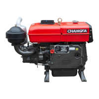
The Changfa 185 Series Diesel Engine is a single-cylinder, horizontal, four-stroke engine designed for various power machinery applications. It can be equipped with either water-evaporative or water-radiator cooling methods, depending on the specific model and user requirements. The engine is designed for reliable and efficient operation, with detailed instructions provided for preparation, starting, running, and shutting down the engine. It also includes components for a lighting generator system, offering either a micro-generator or a flywheel generator to provide electrical power.
Important Technical Specifications
The manual details the technical specifications for different models within the 185 series, including R185(M), CF185(M), JM185(M), and R185N, CF185N, JM185N.
Key specifications include:
- Type: Single-cylinder, horizontal, four-stroke, Water cooling (for R185(M), CF185(M), JM185(M)) or Water-evaporative/Water-radiator (for R185N, CF185N, JM185N).
- Cylinder bore: 85mm
- Piston stroke: 90mm
- Piston displacement: 0.51L
- 12-hour power: 5.88 kW
- 1-hour power: 6.47 kW
- Rating rotation speed: 2200r/min
- Compression ratio: 21
- B. M. E. P.: 628kPa
- Specific Fuel consumption: ≤274.7g/kW • h (for R185(M), CF185(M), JM185(M)) or ≤281.5g/kW • h (for R185N, CF185N, JM185N)
- Injection pressure: 13.5 ± 0.5 MPa
- Starting method: Hand starting (motor starting) or Hand starting.
- Net. Weight: ≤95kg (for R185(M), CF185(M), JM185(M)) or ≤98kg (for R185N, CF185N, JM185N)
- Overall dimensions (L×W×H): 700×390×570 (for R185(M), CF185(M), JM185(M)) or 730×390×570 (for R185N, CF185N, JM185N)
- Valve clearance (cold engine): Intake valve 0.25 ± 0.05mm, Exhaust valve 0.25 ± 0.05mm
- Torque of cylinder head nut: 190 N • m ~ 210 N • m
- Torque of flywheel nut: 260 N • m ~ 300 N • m
- Torque of connecting rod bolts: 70 N • m ~ 90 N • m
- Fuel injector type: P664
- Fuel injector nozzle: ZS4S1A
- Fuel injection pump type: B11-02A fuel injection pump
- Generator: Flywheel AC generator
- Valve Timing:
- Intake valve open: 16° before T. D. C.
- Intake valve close: 38° after B. D. C.
- Exhaust valve open: 50° before B. D. C.
- Exhaust valve close: 14° after T. D. C.
- Fuel injection timing: 16° ± 1° before T. D. C.
Usage Features
The manual emphasizes several key aspects for safe and effective operation:
- Safety Precautions: Users are warned not to touch hot or moving parts, and to keep children, elderly, epileptic individuals, or those with no disposing capacity away from the operating area. The engine should not operate for extended periods without an operator.
- Operating Limits: It is crucial to operate the engine within specified performance limits, avoiding over-speed and over-load conditions. After starting, the engine should idle for 3-5 minutes before running at higher speeds or under load. The governor system's adjusting screw should not be altered to prevent over-speeding.
- Fuel and Lubrication: Only stipulated fuel and lubricating oil should be used, as detailed in the Operation Manual. The lubricating oil in the air filter must be maintained at the required level.
- Cooling System: Saltwater or dirty water should not be used in the water tank. During boiling water operation, the red (or blue) floater in the water tank hopper must not fall below the hopper. In climates below 0°C, cooling water must be drained promptly to prevent cylinder block and head damage.
- Starting Procedure: When starting with a handle, the handle should automatically disengage to prevent it from flying out. The governor handle should be pulled to the "run" position, and the decompression lever moved while cranking the starting shaft, listening for the injector's sound.
- Troubleshooting: In case of trouble, the damaged site should be preserved in its original state and addressed after consulting with a sales agent or repairman.
- Continuous Improvement: The manual notes that the diesel engine is constantly improving, and there may be differences between the manual and the actual engine. Updates will be made in future revisions.
Maintenance Features
The manual provides a detailed maintenance schedule, categorized by daily, 100-hour, and 500-hour intervals:
- Fuel System:
- Daily: Check and fill fuel.
- 100 hours: Clean fuel filter.
- 500 hours: Clean fuel tank and pipeline, check injection pump and injector.
- Lubricating Oil:
- Daily: Check and add oil.
- 100 hours: Clean oil strainer and sump.
- 500 hours: Clean oil bath and pipeline, replace lubricating oil.
- Exhaust and Intake:
- Daily: Clean intake pipe and air filter.
- 500 hours: Clean exhaust pipe and silencer, check valve clearance (daily check if required), check valve leak tightness.
- Cooling Water:
- Daily: Check and add water.
- 100 hours: Keep cooling water running smoothly.
- 500 hours: Replace cooling water, check fan-belt tightness (daily check if required).
- Other Maintenance:
- 500 hours: Check all important bolts and nuts, check piston ring, clean carbon deposits of piston.
Disassembly and Re-assembly:
The manual includes detailed instructions for disassembling and re-assembling key components such as the cylinder head, gearbox cover, balance shaft, camshaft, piston connecting rod assembly, flywheel, and crankshaft. It specifies fastening torques for critical bolts (e.g., cylinder head nuts: 190N.m~210N.m; connecting rod bolts: 70N.m~90N.m) and emphasizes the importance of aligning gear engagement marks during re-assembly. Special attention is given to protecting the crankshaft neck from damage.
Parts Catalog:
The manual provides exploded diagrams and corresponding parts lists for various assemblies, including:
- Engine Body Assembly (Model R185, CF185N, JM185N)
- Condensing Cooling System (Model R185, CF185N, JM185N)
- Cylinder Head Assembly
- Piston Rod Assembly
- Crankshaft Assembly
- Camshaft Assembly
- Balance System
- Intake System
- Exhaust System
- Lubrication System
- Fuel System (Model R185, CF185N, JM185N)
- Governor System (Model R185, CF185N, JM185N)
- Injection Pump Assembly (model B11-02A)
- Injector Assembly (Model P664-00A)
- Motor starting engine parts for R185M, CF185M, and JM185M
An attachment lists spare parts supplied with the engine shipment, such as piston rings, cylinder head gaskets, special wrenches, and a starting handle.
The Changfa Power Machinery Co., Ltd. has met the ISO9002 Quality Assurance System by authentication, indicating a commitment to quality in their manufacturing processes.